Lighting / Fixtures
Installation Manual for George Oliver 12-inch Multi Pendant LED Fixture
A comprehensive installation guide for the George Oliver 12-inch Multi Pendant LED Fixture. This manual provides step-by-step assembly instructions, wiring diagrams, height adjustment procedures, and essential safety warnings for a...
Table of contents
Quick Installation Guide
This document provides instructions for installing the George Oliver 12-inch Multi Pendant LED Fixture. Before beginning, ensure the power is completely off at the fuse box. The manufacturer strongly recommends that a qualified, licensed electrician performs the installation. Always wear gloves during the process to protect the fixture and yourself.
Assembly Instructions
- Unpack: Remove the fixture from its original packaging.
- Separate Components: Separate the mounting plate (1c) from the canopy (2a) by removing the decorative nuts (2c).
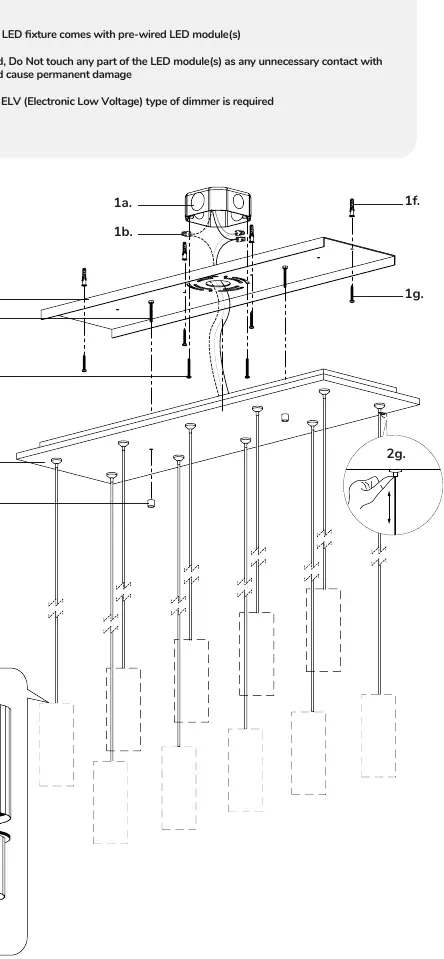
- Mounting Plate: Align the mounting plate screws (1d) to the desired orientation. Attach the mounting plate (1c) to the electrical junction box (1a) using the provided junction box screws (1e).
- Secure to Surface: Secure the mounting plate (1c) to the mounting surface using the provided screws (1g) and anchors (1f).
- Adjust Height: To change the fixture height, push and hold the wire gripper (2g), slide the wire to the desired length, and release the wire gripper (2g) to secure it.
- Electrical Connections: Connect the wires using the provided wire nuts (1b): black to hot (L), white to neutral (N), and ground to GND.
- Final Assembly: Secure the bottom fixture (3b) to the top fixture (3a) by threading them clockwise.
- Attach Canopy: Align and insert the mounting plate screws (1d) through the holes on the canopy (2a) and secure them with the decorative nuts (2c).
Warnings and Cautions
- Power: Ensure power is completely off at the fuse box before starting.
- Dimming: For dimming functionality, an ELV (Electronic Low Voltage) type dimmer is required.
- Handling: Do not touch any part of the LED module(s) unless instructed, as contact could cause permanent damage.
- Input: This fixture is designed for 120V input.
- Mounting: The fixture must be mounted to a correctly installed standard round or octagon box or a wiring box with a plaster frame. The box must be securely mounted to the building structure.
Practical help
Common problems
Fixture does not dim correctly
Ensure you are using an ELV (Electronic Low Voltage) type dimmer.
Difficulty aligning the fixture
Do not mount the fixture directly to the outlet box; use the supplied crossbar and hardware to ensure proper alignment.
Before use
- Ensure power is completely off at the fuse box.
- Verify that you have a qualified licensed electrician for installation.
- Prepare a clear workspace.
- Wear gloves during the entire installation process.
- Confirm the junction box is securely mounted to the building structure.
Images and diagrams
- Illustration 1 shows the assembly sequence, including the junction box (1a), mounting plate (1c), canopy (2a), and wire grippers (2g).
- The diagram details the connection points for the mounting screws (1d, 1g) and the wire nuts (1b).
Model compatibility
- Compatible with standard round or octagon junction boxes.
- Compatible with wiring boxes featuring a plaster frame.

Manual page author
David Miller
Documentation analyst
Organizes user manual content into clear summaries, with attention to model details, product context, and everyday usability.