Lighting / Fixtures
User Manual for Rutec VARDAFLEX LED Strip Paket 2 - Profi
Comprehensive installation and operation guide for the Rutec VARDAFLEX LED Strip Paket 2 - Profi. Includes wiring diagrams, connector assembly steps, safety precautions, and technical specifications.
Table of contents
Manual images
Click an image to enlargeQuick guide from the manual
The Rutec VARDAFLEX LED Strip Paket 2 - Profi is designed for installation in dry indoor rooms. Installation must be performed by a professional electrician to ensure compliance with European safety directives. The system requires a 24V DC power supply and must be operated only when completely unrolled. LED strips should be connected in parallel.
Safety Instructions
- Professional Installation: Installation must be carried out by a qualified electrician.
- Environment: Suitable for dry indoor rooms only.
- Power Supply: Use only a suitable 24V DC power supply.
- Operation: Operate only when completely unrolled.
- Soldering: If soldering, use a temperature of 260°C for a maximum of 10 seconds. Use only neutral cross-linked silicone (never use silicone containing vinegar).
- Repairs: Do not perform repairs yourself; this invalidates the manufacturer's warranty.
Installation
- Prepare the surface: Ensure it is even, clean, dry, and free of dust and grease.
- If the surface is current-carrying, place an insulating layer between the LED strip and the surface.
- Shorten the LED strip if necessary (see Shortening section).
- Remove the protective foil and press the LED strip onto the surface. Do not press directly on the electronic components.
- Connect the LED strip to the power supply.
Shortening the LED Strip
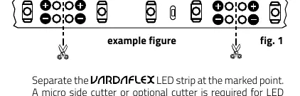
The LED strip can be separated every eight LEDs (62.5 mm). Always switch off the power supply before shortening. Use a micro side cutter or an optional cutter for the marked points.
Mounting the Connector
Follow these steps to assemble the connector:
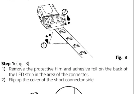
- Remove the protective film and adhesive foil on the back of the LED strip in the connector area.
- Flip up the cover of the short connector side.
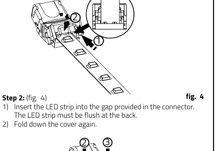
- Insert the LED strip into the gap in the connector, ensuring it is flush at the back.
- Fold down the cover.
- Press the cover down and use a tool (e.g., pliers) to press the connector together until a clicking sound is heard. Repeat on the other side.
- Ensure the plastic cover is not sticking up, indicating the connector is fully closed.
- Insert the cable into the connector, ensuring it is positioned at the back and in the two notches.
- Close the cover again.
- Finally, press the connector together in the center of the cover to ensure proper contact.
Technical Data
- Power Supply: 24 V DC with constant output voltage
- Power: 70 W
- Current: 2.917 A
- Beam Angle: 120°
- Quantity LED: 640
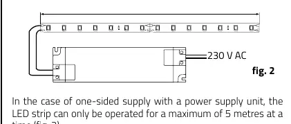
- Length: Maximum 5 meters per connection
- Dimensions: 5000 x 10 x 1.4 mm
- Bending Diameter: 40 mm
Disposal
Dispose of electrical and electronic equipment in an environmentally sound manner. Contact your local authority for more information.
Manufacturer information
rutec Licht GmbH & Co. KG
Practical help
Common problems
LED strip does not light up
Check the power supply connection, ensure 24V DC is provided, and verify the polarity of the connections.
Connector is loose or not making contact
Ensure the plastic cover is fully closed and clicked into place. Verify the LED strip is inserted flush at the back of the connector.
Surface issues
If the mounting surface is conductive, apply an insulating layer. Ensure the surface is clean, dry, and free of grease.
Before use
- Ensure power is switched off before installation.
- Verify the power supply is 24V DC.
- Ensure the surface is clean, dry, and grease-free.
- Unroll the LED strip completely before operation.
- Check that the cable diameter is appropriate for the connection.
Images and diagrams
- Wiring diagram shows the parallel connection of the LED strip to the 24V power supply.
- Connector assembly diagrams illustrate the step-by-step process of inserting the strip and cable into the connector housing.
Model compatibility
- Not waterproof; requires a waterproof housing for outdoor installation.
- Only use neutral cross-linked silicone for mounting.

Manual page author
David Miller
Documentation analyst
Organizes user manual content into clear summaries, with attention to model details, product context, and everyday usability.