Lighting / Controllers & Dimmers
Installation Instructions for GM Lighting ChromaDim 4" 10W Down Light
Quick installation guide for the GM Lighting ChromaDim 4" 10W Down Light. Includes wiring diagrams, hole cutting dimensions, and daisy-chaining instructions for up to 5 units.
Table of contents
Manual images
Click an image to enlargeQuick Installation Guide
The GM Lighting ChromaDim 4" 10W Down Light is designed for recessed installation. Before beginning, ensure the power is turned off at the breaker. This system requires a 5-1/2" diameter hole for mounting. The fixture is IC rated and intended for use with the compatible ChromaDim driver and wall controller. We recommend engaging a qualified and licensed electrician for installation to ensure compliance with NEC and local electrical codes.
Installation Steps
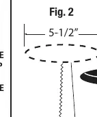
- Prepare the ceiling: Determine the position of the down light and trace a 5-1/2" diameter circle on the surface material. Use a keyhole saw or 5-1/2" hole saw to cut the opening.
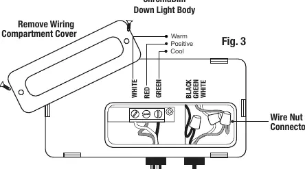
- Wiring: For the first down light in the run, connect the White, Red, and Green leads from the ChromaDim Driver to the corresponding White, Red, and Green leads on the down light. You may use the supplied Wago connectors.
- Mounting: Compress the spring clips on the fixture body and push the unit up into the ceiling hole. Ensure a firm fit.
- Additional Fixtures: For subsequent down lights, use the quick connects to add more fixtures to your run.
Multiple Unit Installation
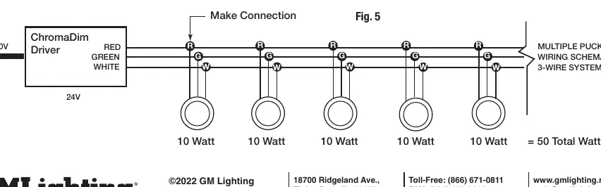
You can install up to 5 ChromaDim 10W Down Lights on a single lead. When planning your layout, ensure ample distance between down lights. Follow the wiring schematic provided in the manual to maintain the 3-wire system (White, Red, Green) across all units.
Safety and Compatibility
- Electrical: Ensure both the wall switch and LED driver are grounded according to local codes.
- Compatibility: All system parts are compatible and designed to work together. Do not attempt to swap out products from other manufacturers.
- Environment: Do not install in applications outside the listed ambient temperature or in areas that are not easily accessible for service.
Practical help
Common problems
Fixture does not fit in the ceiling hole
Ensure the hole cut is exactly 5-1/2" in diameter.
Wiring connections are loose or not working
Verify that the White, Red, and Green leads are securely connected using the supplied Wago connectors or wire nuts.
System not powering on
Check that the power is turned on and that the ChromaDim driver and wall controller are connected per their specific instructions.
Before use
- Turn off power at the breaker before starting installation.
- Check local electrical codes.
- Ensure you have a keyhole saw or 5-1/2" hole saw.
- Verify you have a Phillips screwdriver.
- Confirm the installation area is accessible for future service.
- Ensure the ChromaDim driver and wall controller are available.
Specs in practice
- Daisy-chain limit
- Maximum of 5 units (10W each) per lead.
- Wiring System
- 3-wire system using White, Red, and Green leads.
Images and diagrams
- Fig 2: Shows the 5-1/2" hole cutting process.
- Fig 3: Details the wiring compartment and lead connections.
- Fig 4: Illustrates the spring clip compression for ceiling insertion.
- Fig 5: Wiring schematic for connecting multiple puck lights in a 3-wire system.
Model compatibility
- Only use with compatible GM Lighting ChromaDim system parts.
- Do not swap with other manufacturers' products.
- Down light is IC rated.

Manual page author
David Miller
Documentation analyst
Organizes user manual content into clear summaries, with attention to model details, product context, and everyday usability.