Home Appliances / Commercial Kitchen Equipment
Parts List and Circuit Diagram for Hendi Heated Countertop Display 120Ltr
Access the official parts list, exploded view diagram, and circuit schematic for the Hendi Heated Countertop Display 120Ltr. This technical document is essential for identifying replacement parts, understanding assembly, and...
Table of contents
Manual images
Click an image to enlargeQuick Guide
This document serves as a technical reference for the Hendi Heated Countertop Display 120Ltr. It contains an exploded view of the unit, a comprehensive Bill of Materials (BOM) for identifying replacement parts, and a circuit diagram for electrical troubleshooting. This manual is intended for service technicians and owners performing maintenance.
Exploded View and Parts Identification
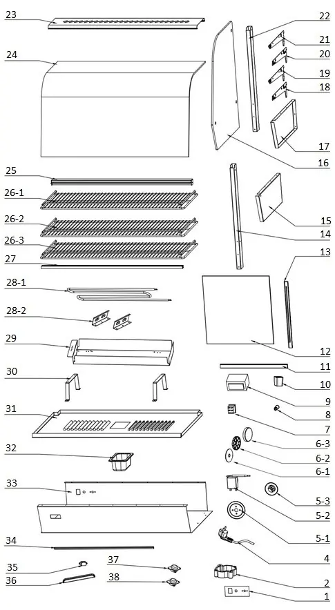
The exploded view provides a visual breakdown of the unit's assembly, including glass panels, shelving, heating elements, and control components. Each component is numbered, corresponding to the Bill of Materials table on page 2. Use this diagram to understand the physical structure of the display case and the correct placement of parts during reassembly.
Bill of Materials (BOM)
The BOM table lists all critical components of the 120Ltr display. Key information includes:
- Item Number: Corresponds to the exploded view.
- Description: Name of the part.
- Part Number: Official Hendi part number for ordering replacements.
- Remarks: Specific details such as dimensions for shelves (e.g., 63.5 x 33.5cm) or technical specifications for the power cord (H05RN-F 3G0.75mm).
Note: Items marked as 'nss' are not sold separately, and 'n/a' indicates the part is not available as a standalone spare.
Circuit Diagram
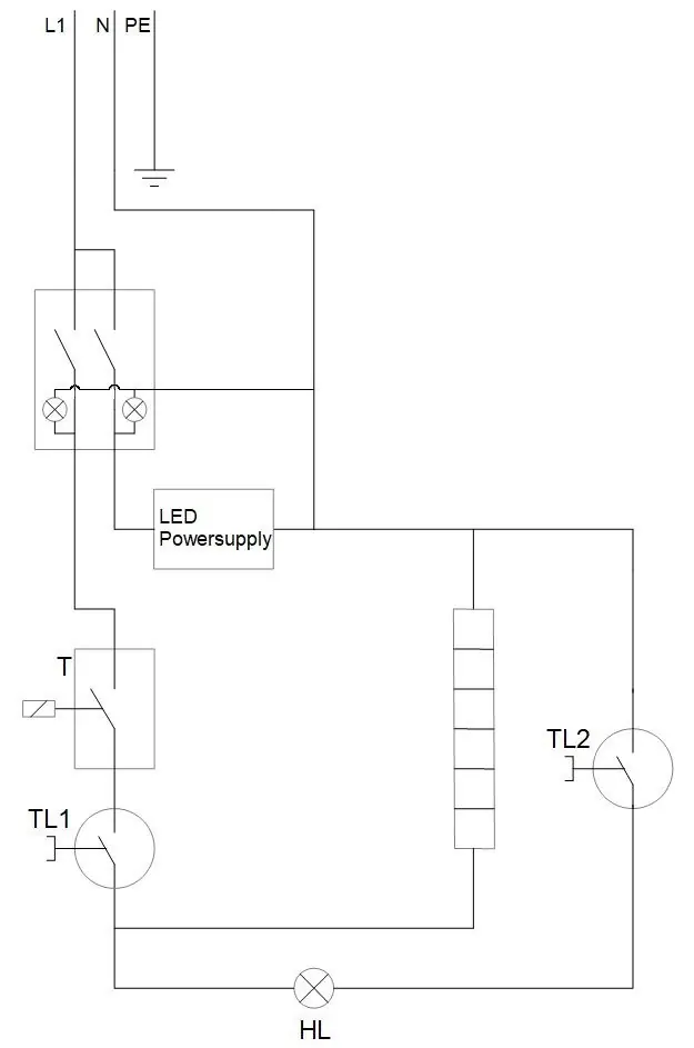
The circuit diagram illustrates the electrical wiring of the unit. It shows the path from the power input through the switches, LED power supply, thermostat, and heating elements. This diagram is crucial for diagnosing electrical faults, such as heating failures or lighting issues.
Safety and Maintenance
The unit includes two thermal protection devices (Clixons):
- Clixon 150°C (Manual Reset): A safety cut-out that requires manual intervention if the unit overheats.
- Clixon 125°C (Auto-reset): A safety cut-out that resets automatically once the unit cools down.
Always ensure the unit is disconnected from the power supply before performing any maintenance or replacing parts.
Manufacturer information
HENDI Tools for Chefs
Practical help
Common problems
Unit does not heat up
Check the heating element (28-1), thermostat (5-2), and ensure the manual reset Clixon (37) has not tripped.
LED lights not working
Inspect the LED light (34) and the LED power supply unit. Verify connections according to the circuit diagram.
Unit overheats or shuts down unexpectedly
Check the Clixon thermal cut-outs (37 and 38). If the 150°C manual reset Clixon has tripped, it must be manually reset.
Before use
- Verify the model number 120LTR matches your specific unit.
- Ensure the power cord (4) is securely connected and undamaged.
- Check that all glass panels (16, 24) are correctly seated in the door frames.
- Ensure the water tank (32) is in place if humidity control is required.
- Disconnect power before opening the housing or inspecting internal components.
Specs in practice
- Clixon 150°C (Manual Reset)
- Safety thermal cut-out switch that requires manual reset if the unit overheats.
- Clixon 125°C (Auto-reset)
- Safety thermal cut-out switch that resets automatically once the unit has cooled.
- Water Tank GN1/9
- Removable container used for maintaining humidity inside the display.
- Power Cord H05RN-F 3G0.75mm
- Standard heavy-duty rubber-sheathed cable suitable for commercial kitchen equipment.
Images and diagrams
- The exploded view (Page 1) shows the assembly order of the glass panels, shelves, and heating elements.
- The circuit diagram (Page 3) illustrates the wiring path from the power input through the thermostat and heating elements.
Model compatibility
- Parts listed are specific to the 120Ltr model with batch numbers 000000 and up.
- Some components (marked 'nss') are not sold separately and may require replacing the entire assembly.

Manual page author
David Miller
Documentation analyst
Organizes user manual content into clear summaries, with attention to model details, product context, and everyday usability.