Tools / Power Tools
User Manual for Hercules 13A Trigger Grip Angle Grinder
Quick guide for the Hercules 13A Trigger Grip Angle Grinder (Model HE65). Includes setup, safety warnings, accessory installation, operation, and troubleshooting.
Table of contents
Manual images
Click an image to enlargeQuick guide from the manual
The Hercules 13A Trigger Grip Angle Grinder (Model HE65) is a high-power tool designed for grinding, sanding, wire brushing, and cutting. Before use, ensure the tool is inspected for damage, the correct wheel guard is installed, and you are wearing appropriate personal protective equipment (PPE). Always disconnect the power supply before performing any maintenance or changing accessories.
Safety Warnings
- General Safety: Keep work area clean and well-lit. Do not operate in explosive atmospheres. Keep children and bystanders away.
- Electrical Safety: Ensure the plug matches the outlet. Do not modify the plug. Use a GFCI-protected supply in damp locations.
- Kickback: Kickback is a sudden reaction to a pinched or snagged accessory. Maintain a firm grip, use the auxiliary handle, and avoid positioning your body in the path of the tool if kickback occurs.
- Specific Operations: Do not use accessories not designed for the tool. Ensure the rated speed of the accessory is at least equal to the tool's maximum speed.
Tool Set Up
Adjusting the Wheel Guard
- Pull out the Wheel Guard Lock Lever.
- Rotate the Wheel Guard to the desired position to shield yourself.
- Push the Wheel Guard Lock Lever back into place to secure it.
- Verify the guard is firmly in place before proceeding.
Installing Auxiliary Side Handle
- The handle can be installed on either side of the Gear Housing.
- Screw the threaded end of the Side Handle clockwise into the selected socket.
- Tighten securely before use.
Operation
Starting the tool: Push the Lever forward and squeeze the Trigger. To turn the tool OFF, release the Trigger.
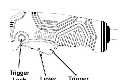
Continuous operation: Push the Lever forward, squeeze the Trigger, and depress the Trigger Lock. To turn OFF, squeeze the Trigger to release the lock, then release the Trigger.
Usage: Allow the tool to reach full speed before touching the workpiece. For grinding/sanding, apply at a 10°–15° angle. For cutting, apply straight into the material using only the edge of the wheel.
Accessory Installation
Installing Grinding/Cut-Off Wheels:
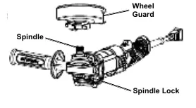
- Press and hold the Spindle Lock to prevent the spindle from turning.
- Remove the Flange Nut, keeping the Flange in position.
- Place the wheel on the spindle.
- Thread the Flange Nut onto the spindle and tighten with the wrench. Do not overtighten.
Installing Threaded Accessories:
- Press and hold the Spindle Lock.
- Remove the Flange Nut and Flange.
- Thread the accessory firmly onto the spindle and tighten with the wrench.
Maintenance
- Before each use: Inspect for loose hardware, misalignment, binding, damaged cords, or cracked parts.
- After use: Wipe external surfaces with a clean cloth.
- Cleaning: Periodically blow dust out of motor vents using dry compressed air. Wear safety goggles and breathing protection.
Practical help
Common problems
Tool will not start
Check if the cord is plugged in, check the power outlet/circuit breaker, or press the thermal reset button on the tool.
Tool operates slowly
Decrease pressure on the workpiece or eliminate the use of an undersized extension cord.
Overheating
Allow the tool to work at its own rate, clean blocked motor vents, or stop using an undersized extension cord.
Tool does not grind/sand effectively
Ensure the disc accessory is the correct type, in good condition, and the Flange Arbor Nut is tight.
Before use
- Inspect the tool for loose hardware or damaged parts.
- Ensure the wheel guard is properly installed and secured.
- Verify the trigger is in the OFF position before plugging in.
- Check that the accessory is rated for at least 10,000/min.
- Ensure the accessory size matches the installed guard size.
- Wear ANSI-approved eye and hearing protection.
Specs in practice
- Electrical Rating
- 120VAC / 60Hz / 13A
- No Load Speed
- 10,000/min
- Spindle Thread
- 5/8"-11 TPI
- Accessory Diameters
- Compatible with 4-1/2" (115mm), 5" (125mm), and 6" (150mm) guards.
Images and diagrams
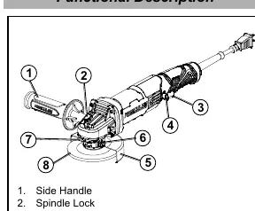
- Functional Description: Identifies the side handle, spindle lock, trigger, trigger lock, wheel guard, and bolt.
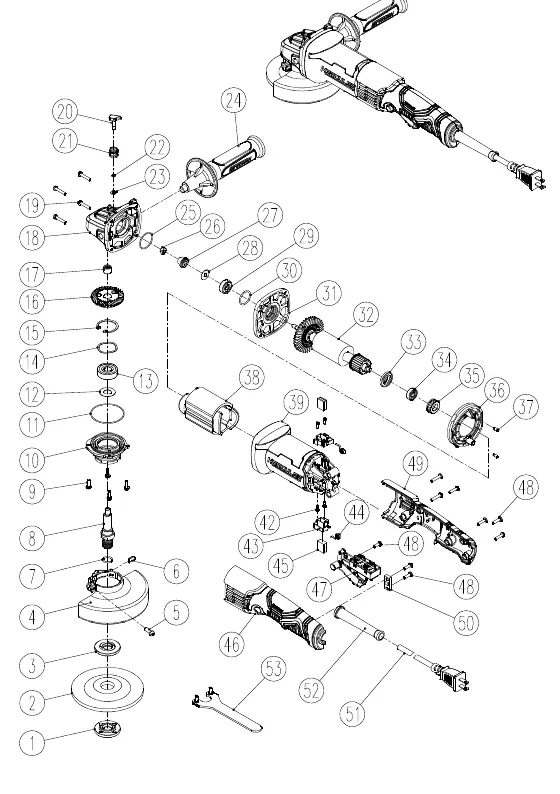
- Assembly Diagram: Exploded view showing the internal components and assembly order.
Model compatibility
- Use only 4.5" grinding wheels with 4.5" guards.
- Use only 5" grinding wheels with 5" guards.
- Use only 6" grinding wheels with 6" guards.

Manual page author
Emily Carter
User documentation editor
Prepares concise manual descriptions and highlights the most useful setup, operation, and maintenance information for readers.