Electronics / Signal Boosters
User Manual for HiBoost Home 10K Mobile Signal Booster
Quick guide for the HiBoost Home 10K Mobile Signal Booster. Learn how to install the outdoor and indoor antennas, configure the booster, interpret LCD and LED status indicators, and troubleshoot signal issues.
Table of contents
Manual images
Click an image to enlargeQuick Guide from the Manual
The HiBoost Home 10K is designed to improve mobile signal in homes and offices. Proper installation is critical for performance. Key requirements include maintaining at least 20 feet of vertical separation between the indoor and outdoor antennas and ensuring the outdoor antenna is pointed toward the nearest cellular tower. Before use, you must register this device with your wireless provider.
What's Included
- Home 10K Signal Booster
- Outdoor Wide Band Directional Antenna
- Indoor Wide Band Panel Antenna
- 12V/3A AC/DC Power Supply
- Pole and Wall Mount Bracket
- Wall Mount Bracket
- 2x 30 ft HiBoost200 Low-loss Cable
- Booster Mount Hardware
How It Works
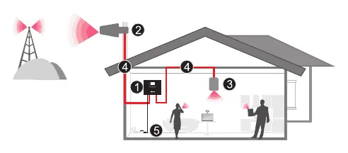
The outdoor antenna receives the signal from the nearest cellular tower and transmits it to the booster. The booster amplifies the signal and sends it to the indoor antenna, which retransmits it to your mobile device. The process works in reverse for outgoing signals.
Installation Preparation
Before starting, ensure you have a Phillips screwdriver, a drill, and a mobile phone to test signal strength. Plan your layout to ensure the booster is near an electrical outlet, well-ventilated, and away from excessive heat, moisture, or direct sunlight.
Installation Steps
1. Find the Location
Identify the location with the strongest received signal. You can use the LCD display on the booster or a mobile phone app to test signal strength at different points on the roof.
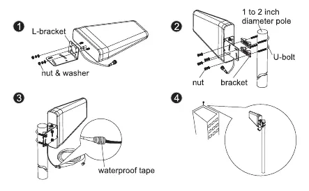
2. Install Outdoor Antenna
Mount the outdoor antenna on the roof using the provided L-bracket and U-bolt. Ensure it is pointed toward the cellular tower and is as far away as possible from the planned indoor antenna location.
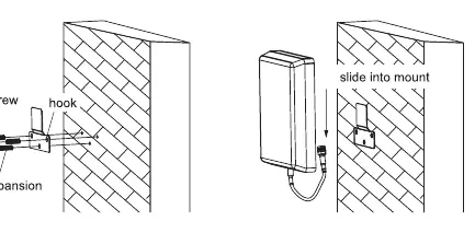
3. Install Indoor Antenna
Select a location on a wall where you need better reception. Mount the indoor antenna using the included screws and hooks.
4. Install Signal Booster
Mount the booster in an easily accessible area on a wall near a power outlet. Use a surge protector rated at a minimum of 1000 Joules.
5. Run Coaxial Cable
Connect the cables from the outdoor antenna to the port marked 'Outdoor' and the indoor antenna to the port marked 'Indoor'. Tighten connections by hand and use waterproof tape on outdoor connections.
6. Power Up
Plug the power adapter into the booster and then into an AC outlet. The LED indicator should light up green.
Signal Booster Status
LCD Features
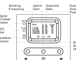
The LCD screen displays real-time uplink and downlink gain (dB) and output power (dBm). It also features indicators for:
- ISO: Flashes when there is not enough isolation between antennas.
- ALC: Flashes when the booster is receiving too much signal.
- OFF: Indicates the booster has shut off in a specific band due to oscillation or overload.
LED Status
- Power LED: Green (Normal), Off (DC power problem).
- Alarm LED: Green (Normal), Slow Flashing Green (Full output power), Quick Flashing Green (Output power too high), Quick Flashing Red (Shut off due to excessive signal).
- ISO LED: Green (Normal), Slow Flashing Green (Slight loop back), Quick Flashing Green (Deep loop back), Quick Flashing Red (Shut off due to severe self-oscillation).
Troubleshooting
- Flashing ISO: Increase distance between antennas, use barriers, or reduce downlink gain using manual controls.
- Flashing ALC: Adjust antenna direction to lower received signal or reduce downlink gain.
- Poor Coverage: Ensure the outdoor antenna is pointed correctly, try a higher gain antenna, or add more indoor antennas.
Specifications
- Max Gain: 65 dB
- Max Output Power: 12 dBm
- Frequency Range: Supports 700MHz, 800MHz, 1900MHz, and 2100MHz bands.
- Power Supply: Input AC 100-240V, Output DC 12V/3A.
- Dimensions: 8.6 x 6.5 x 2 inches.
Product Warranty
The product includes a 30-day money-back guarantee and a 3-year warranty. The warranty does not cover damage caused by misuse, abuse, neglect, or failure to use a surge-protected AC power strip.
Practical help
Common problems
ISO LED flashing
Indicates oscillation. Increase vertical or horizontal distance between antennas, use walls as barriers, or reduce downlink gain.
ALC LED flashing
Indicates signal overload. Adjust antenna direction to lower received signal or reduce downlink gain.
Power LED off
Check the power supply connection to the booster and the wall outlet.
Poor coverage
Check outdoor antenna alignment, try a higher gain antenna, or add more indoor antennas.
Before use
- Ensure sufficient cable length between antennas and booster.
- Verify the booster is near an electrical outlet.
- Plan the layout to ensure maximum separation between indoor and outdoor antennas.
- Register the device with your wireless provider.
- Ensure the booster is installed in a well-ventilated area away from heat/moisture.
Specs in practice
- Max Output Power
- 12 dBm (downlink).
- Frequency Range
- Supports 700MHz, 800MHz, 1900MHz, 2100MHz bands.
- Power Supply
- Input AC 100-240V, Output DC 12V/3A.
Images and diagrams
- LCD Display: Shows real-time uplink/downlink gain and output power.
- LED Indicators: Power, Alarm, and ISO status lights.
- System Layout: Outdoor antenna -> Coaxial Cable -> Booster -> Indoor Antenna.
Model compatibility
- Must be registered with wireless provider before use.
- For indoor use only.
- Requires 20 feet of vertical separation between antennas.

Manual page author
Michael Turner
Technical manual editor
Reviews PDF manuals for structure, safety notes, and practical product details so readers can find the right information quickly.