Electronics / Signal Boosters
Installation Guide for HiBoost 10K Smart Link Signal Booster
A comprehensive installation and setup guide for the HiBoost 10K Smart Link signal booster. Includes instructions for antenna placement, app configuration, LED status indicators, and troubleshooting signal issues.
Table of contents
Manual images
Click an image to enlargeQuick Guide from the Manual
The HiBoost 10K Smart Link is designed to improve cellular signal strength. The installation process requires identifying the nearest cell tower, mounting the outdoor antenna, connecting the booster, and configuring the system via the Signal Supervisor App. Ensure you have at least one stable bar of signal outside your home before installation, as the device will not function in areas with extremely weak signals.
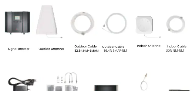
Package Contents
The package includes the signal booster, outdoor antenna, indoor antenna, power supply, various cables (outdoor and indoor), Bluetooth/Wi-Fi antenna, and mounting accessories including waterproof tape.
Getting Started
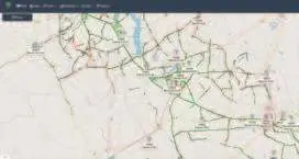
Before physical installation, download the Signal Supervisor App to register your booster. Use the app to identify your frequency band and locate the nearest cell tower. For Android, use the NetWork Cell Info Lite app; for iOS, use Field Test Mode (dial *3001#12345#*). Take screenshots of the tower location and signal data to assist with antenna alignment.
Installation Steps
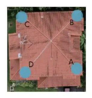
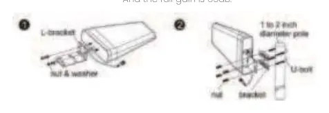
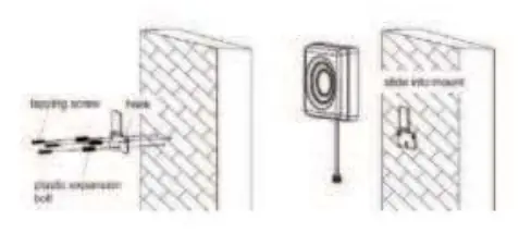
1. Antenna Placement: Place the outdoor antenna at one of the four ends of your roof, ensuring there are no barriers between the antenna and the cell tower. Point the antenna toward the tower.
2. Wiring: Connect the outdoor antenna to the booster using the provided cables. Do not connect the indoor antenna at this stage.
3. Adjustment: Power on the booster and observe the signal readings in the app. Adjust the outdoor antenna position to maximize output power. The full output power for the 10K Smart Link is 12dBm.
4. Indoor Setup: Connect the indoor antenna and point it toward the area you wish to cover. Ensure the indoor and outdoor antennas face opposite directions to prevent loopback interference.
5. Testing: Perform a signal quality test by comparing speed tests and signal bars with the booster on and off.
LED Status Indicators
The booster features ALARM, Power, and ISO LEDs to indicate system health:
- ALARM LED: Solid green indicates normal operation. Flashing green or red indicates overload; adjust the outdoor antenna away from the tower.
- ISO LED: Solid green indicates normal operation. Flashing green or red indicates loopback; increase the distance between indoor and outdoor antennas or add barriers.
- Power LED: Green indicates normal power; off indicates a DC power problem.
Troubleshooting
If the booster is not working correctly, check the LED patterns. For overload, point the outdoor antenna slightly away from the tower. For loopback, increase the vertical and horizontal separation between antennas. For poor signal, ensure the outdoor antenna is aimed at the best tower and that there are no obstructions.
Technical Specifications
The 10K Smart Link operates with a maximum gain of 65 dB and a maximum output power of 12 dBm. It requires a 12V/3A power supply and has an impedance of 50 ohm. The device is rated IP40 for environmental conditions.
Practical help
Common problems
Alarm light blinking green or red (Overload)
The outdoor signal is too strong. Point the outdoor antenna slightly away from the cell tower.
ISO light blinking green or red (Loop Back)
Inadequate separation between antennas. Increase vertical and horizontal distance, make antennas face opposite directions, or add barriers like walls.
Alarm and ISO lights solid green but no boosted signal
The band may not be supported or the signal is from other carriers. Check the band in the Signal Supervisor app and ensure it is supported.
Poor Signal (Alarm and ISO solid green)
Input signal is too weak. Adjust the outdoor antenna to the best direction, try another tower, or increase the height of the outdoor antenna.
Before use
- Download the Signal Supervisor App.
- Identify your frequency band using network tools (NetWork Cell Info Lite for Android or Field Test Mode for iOS).
- Locate the nearest cell tower.
- Ensure you have at least one stable bar of signal outside the house.
- Prepare mounting tools for the antennas and booster.
Specs in practice
- Maximum Gain
- 65 dB
- Maximum Output Power
- 12 dBm
- Power Supply
- Input AC 100-240V, Output DC 12V/3A
Images and diagrams
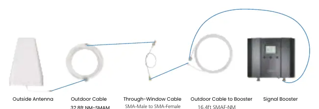
- The wiring diagram illustrates the connection sequence: Outdoor Antenna -> Outdoor Cable -> Through-Window Cable -> Outdoor Cable to Booster -> Signal Booster.
- The antenna placement diagram shows the four corners of a roof as recommended installation points.
Model compatibility
- The booster will not work in areas with extremely weak signals (less than 1 bar outside).
- Ensure the indoor and outdoor antennas are separated by sufficient distance or barriers to prevent loopback.

Manual page author
David Miller
Documentation analyst
Organizes user manual content into clear summaries, with attention to model details, product context, and everyday usability.