Lighting / Fixtures
Hidealite LiteTrac 1-Phase Track Lighting System Installation Guide
Comprehensive installation guide for the Hidealite LiteTrac 1-Phase track lighting system. Includes safety instructions, component overview, wiring examples, and cover installation steps.
Table of contents
Manual images
Click an image to enlargeQuick Guide and Safety
The Hidealite LiteTrac 1-Phase track lighting system must be installed by a licensed electrician in accordance with local regulations. Always ensure the power is disconnected before commencing any installation or maintenance work.
System Components
The LiteTrac system consists of various modular components designed for 1-phase electrical configurations. Key components include:
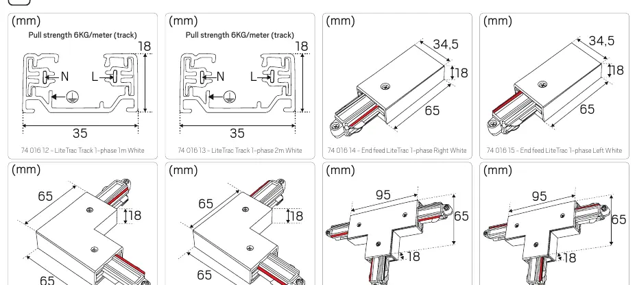
- Tracks: Available in 1m and 2m lengths.
- Feeds: End feed (Left/Right), L-feed (Inner/Outer), T-feed (Inner/Outer), X-feed, and Middle feed.
- Connectors: Straight connectors, adjustable corner connectors, and monopoint adapters.
- Accessories: End caps (included with tracks), covers, and adapters with strain relief.
Installation Overview
The system is modular and allows for flexible configurations. When planning the layout, ensure the mounting surface can support the track weight. The maximum pull strength for the track is 6kg per meter.
Wiring and Connections
The system uses a standard 1-phase connection. Ensure that the Neutral (N) and Live (L) wires are correctly connected to the corresponding terminals in the feed components. Refer to the markings on the connectors to ensure proper polarity.
Cover Installation
To install the cover on the track:
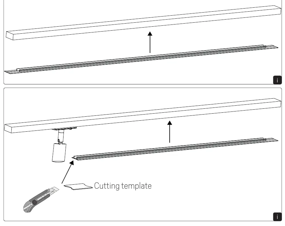
- Measure the required length of the cover.
- Use the provided cutting template to cut the cover to the correct size.
- Snap the cover into the track profile.
Practical help
Common problems
System does not power on
Verify that the power supply is connected and that the Neutral (N) and Live (L) wires are correctly seated in the feed terminals.
Track feels loose or unstable
Ensure the mounting surface is solid and that the track is securely fastened. Do not exceed the maximum pull strength of 6kg/meter.
Before use
- Ensure the main power supply is disconnected.
- Verify that the installation is performed by a licensed electrician.
- Check that the mounting surface can support the track weight.
- Confirm all components are compatible with the 1-phase system.
- Ensure all end caps are installed on open track ends.
Specs in practice
- Pull strength
- The maximum load capacity of the track is 6kg per meter.
Images and diagrams
- The installation example diagram illustrates how to connect various feeds (L, T, X, Middle) to the track to create a custom lighting layout.
- The cover installation diagram shows the process of cutting the cover using a template and snapping it into the track.
Model compatibility
- This system is strictly for 1-phase electrical installations.
- Tracks are delivered with 2 end caps included.

Manual page author
David Miller
Documentation analyst
Organizes user manual content into clear summaries, with attention to model details, product context, and everyday usability.