Lighting / Fixtures
Installation Guide for Hubbardton Forge Brooklyn Multiport Rectangle 10lt Pendant 131205
Step-by-step installation guide for the Hubbardton Forge Brooklyn Multiport Rectangle 10lt Pendant (131205). Includes canopy mounting, wiring instructions, fixture height adjustment, and shade/glass assembly.
Table of contents
Manual images
Click an image to enlargeQuick Guide and Safety Information
This document provides installation instructions for the Hubbardton Forge Brooklyn Multiport Rectangle 10lt Pendant (131205). Important: Installation should be performed by a licensed electrician in accordance with local codes. Ensure power is turned off at the main breaker box before beginning. The fixture must be attached to a structural member in the ceiling; do not rely on anchors alone to suspend the fixture.
Component Parts
Before starting, verify you have all components:
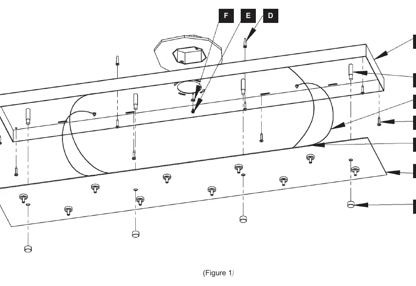
- Canopy (A), Canopy Cover Plate (B), #10 Screws (C), Anchors (D), Ground Screw (E), Cupped Washer (F)
- Safety Cable (G), Safety Cable Nut (H), Studs (I), Gripper (10) (J), Supply/Support Cable (10) (K)
- Transformer (L), Wire Connector (8) (M), Cap (4) (N), Fixture (10) (O), Collar (10) (P), Socket (10) (Q)
- Accent Shade (20) (R), Nut (20) (S), Bulb (10) (T - sold separately), Glass (10) (U)
Canopy Installation
- Unpack the canopy and fixture. Remove caps (N) from studs (I) and set the cover plate (B) aside.
- Place the canopy (A) over the electrical box to mark mounting hole locations.
- Drill 1/4" holes at marked locations and insert anchors (D).
- Thread wires through the canopy (A) and fasten it to the electrical box using machine screws (not provided).
- Secure the canopy (A) to a structural member in the ceiling using wood screws (C).
- Attach a pigtail lead to the canopy (A) using the ground screw (E) and cupped washer (F).
- Connect transformer wires to supply wires (white to white, black to black) and connect all ground wires. Ensure wire connectors are twisted securely and no bare wire is exposed.
- Raise the canopy cover plate (B), slide safety cables (G) over studs, and reattach nuts (H) to temporarily suspend the plate while making further connections.
Fixture Installation and Wiring
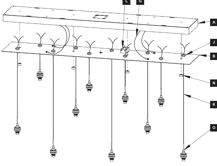
- Unpack fixtures (O). Twist wires together and slide them through the gripper (J) in the canopy cover plate (B).
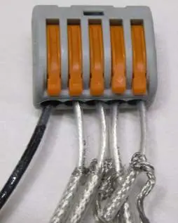
- Using provided wire connectors (M), connect stranded fixture wires to each other and then to the wire connector attached to the red transformer (L) wire.
- Repeat the process for braided fixture wires, connecting them to the other red transformer (L) wire.
- Align the canopy cover plate (B) with studs (I) in the canopy (A) and secure using caps (N). Ensure no wires are pinched.
- Push the supply/support cable (K) into the gripper (J) to adjust the fixture height. To reduce length, push up on the gripper plunger while pulling the cable.
Shade and Glass Installation
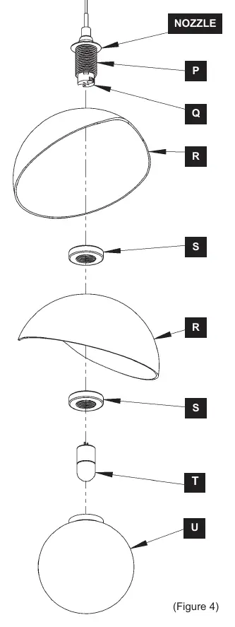
- Remove nuts (S) from the collar (P).
- Slide the first accent shade (R) over the collar (P) and secure with a nut (S).
- Slide the second accent shade (R) over the collar (P) and secure with the second nut (S).
- Install the bulb (T) into the socket (Q).
- Carefully thread the glass (U) onto the collar (P).
- Repeat for all remaining fixtures. Restore electricity at the main breaker.
Practical help
Common problems
Fixture height needs adjustment
Push up on the gripper (J) plunger while gently pulling the supply/support cable (K) to adjust the length.
Wires pinched during assembly
Ensure no wires are trapped between the canopy (A) and the cover plate (B) when raising the plate to the canopy.
Missing parts
Contact the dealer from which the product was purchased for assistance.
Before use
- Turn off power at the main breaker box.
- Ensure the ceiling structure can support the weight of the fixture.
- Verify all parts (A-U) are present.
- Have a licensed electrician available for installation.
- Ensure you have necessary tools: drill, hammer, pencil, and wire connectors.
Images and diagrams
- Figure 1: Canopy installation and mounting points.
- Figure 2: Fixture layout and wiring routing.
- Figure 3: Wiring diagram for stranded and braided fixture wires.
- Figure 4: Assembly sequence for shades, bulbs, and glass.
Model compatibility
- Bulbs (T) are sold separately.
- Wood screws are supplied, but different construction materials may require different fasteners.
- Do not exceed the maximum wattage noted on the fixture.

Manual page author
Michael Turner
Technical manual editor
Reviews PDF manuals for structure, safety notes, and practical product details so readers can find the right information quickly.