Plumbing / Sump Pumps
User Manual for Little Giant 15SC-CIA-RF Sewage Pump
Quick guide for the Little Giant 15SC-CIA-RF sewage pump. Includes performance specifications, construction details, and operational data for wastewater and sewage removal.
Table of contents
Manual images
Click an image to enlargeKey Information for the Little Giant 15SC-CIA-RF
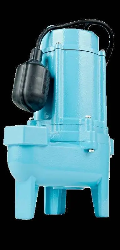
This document provides technical specifications and performance data for the Little Giant 15SC-CIA-RF sewage pump. This unit is designed for wastewater and sewage removal, dewatering, and water transfer. It features a 3/4 HP motor and is capable of passing 2-inch solids.
Product Overview
The 15SC-CIA-RF is a fully automatic, submersible sewage pump. It is designed for continuous duty operation and includes a remote float switch with a piggy-back plug for automatic control.
Technical Specifications
- Motor: 3/4 HP Permanent Split Capacitor (PSC), thermally protected.
- Discharge: 2-inch FNPT.
- Electrical: 115V, 60Hz, 11A, 1200W.
- Cord Length: 20 feet (6.1 m).
- Performance: 130 GPM at 5' head; 40 GPM at 25' head.
- Shut-Off Head: 28 feet (8.53 m).
Construction Details
- Motor Housing: Cast Iron.
- Volute: Cast Iron.
- Impeller: Polymer, clog-resistant.
- Motor Shaft: Stainless Steel.
- Fasteners: Stainless Steel.
- Bearings: Ball Bearing (upper and lower).
- Shaft Seal: Mechanical.
Performance Data
The pump performance is defined by the relationship between Total Dynamic Head (feet) and Flow Capacity (Gallons Per Minute). At 0 feet of head, the pump delivers 140 GPM. As the head increases to 25 feet, the capacity decreases to 40 GPM. The maximum shut-off head is 28 feet.
Practical help
Common problems
Pump fails to start
Verify the float switch operation. The pump is designed to turn on at 17-20 inches and off at 10-12 inches.
Reduced flow rate
Check the discharge pipe for obstructions. While the impeller is clog-resistant, ensure the discharge path is clear.
Before use
- Verify power supply is 115V, 60Hz.
- Ensure the discharge pipe is 2-inch FNPT.
- Check that the float switch has adequate clearance to operate (17-20 inches on, 10-12 inches off).
- Confirm the application is suitable for wastewater or sewage removal.
- Ensure the pump is fully submerged for continuous duty operation.
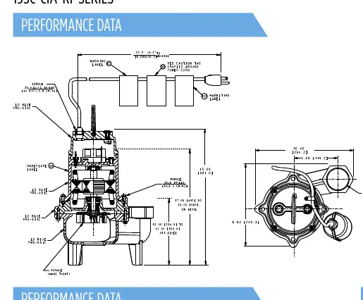
Images and diagrams
- The performance curve graph illustrates the flow capacity in GPM relative to the Total Dynamic Head in feet.
- The dimension diagram provides the physical footprint and discharge location for installation planning.
Model compatibility
- Designed for continuous duty operation.
- Capable of passing 2-inch solids.

Manual page author
Emily Carter
User documentation editor
Prepares concise manual descriptions and highlights the most useful setup, operation, and maintenance information for readers.