Plumbing / Sump Pumps
Little Giant 14S and 16S Series Submersible Pump Owner's Manual
Quick guide for the Little Giant 14S and 16S series submersible pumps. Includes installation steps, electrical connection diagrams, maintenance procedures, and troubleshooting tips.
Table of contents
Manual images
Click an image to enlargeQuick Guide from the Manual
The Little Giant 14S and 16S series are submersible pumps designed for use in basins or lift stations for sewage wastewater transfer and dewatering. These pumps are capable of handling 2-inch (50.8 mm) spherical solids. Always ensure the pump is connected to a properly grounded circuit, preferably with GFCI protection if required by local codes. Do not run the pump dry, as this can cause overheating and damage.
Safety Instructions
Danger: Risk of death, personal injury, or property damage due to explosion, fire, or electric shock. Do not use to pump flammable, combustible, or explosive fluids. Do not handle the pump with wet hands or while standing in water. Always disconnect power before servicing.
Warning: High voltages are present. Ensure the pump is connected to a circuit with adequate capacity. Do not use an extension cord. If the pump is hardwired, ensure the junction box is located where it cannot be flooded or submerged.
Installation
Physical Installation:
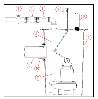
- Install the pump in a gas-tight basin at least 18 inches (45.72 cm) in diameter and 30 inches (76.2 cm) deep.
- Ensure the sump is clean and free of debris.
- Connect discharge piping using pipe joint compound or PTFE tape at all threaded connections.
- Install a union in the discharge line just above the basin cover.
- Install a full-flow check valve in the discharge line, positioned horizontally or at an angle no greater than 45 degrees.
- Install a gate valve in the discharge line.
- Drill an air relief bleed hole (1/8 inch or 3/16 inch) in the discharge pipe at a 45-degree angle below the horizontal plane to prevent air locks.
- Install a separate sump vent.
Electrical Connections:
- Connect the power cord to a constant source matching the pump nameplate voltage.
- The pump must be on its own circuit with no other equipment.
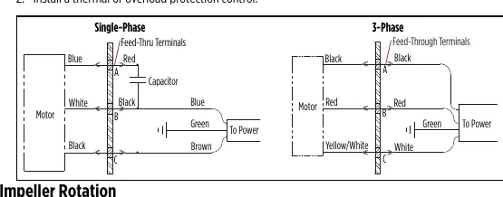
- For 3-phase pumps, ensure the impeller rotates counter-clockwise. If rotation is incorrect, interchange any two of the white, red, or black wires at the disconnect box.
Maintenance
Periodic Service: Inspect the system every three months (more frequently for heavy use). Check power cords for damage, remove debris from the basin, and ensure all flexible coupling hose clamps are tight.
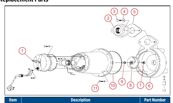
Cleaning Impeller and Volute:
- Disconnect power.
- Remove the four bolts holding the volute to the motor housing.
- Separate the volute and clean the impeller and volute passage.
- Ensure the impeller turns freely.
- Reattach the volute.
Troubleshooting
If the pump does not turn on, check if it is plugged in, if the circuit breaker is tripped, or if there is an accumulation of trash on the float. If the pump runs but does not discharge liquid, check if the check valve is installed backwards or if the pump is air-locked (clean the air bleed hole). If the pump cycles continuously, ensure a check valve is installed in the discharge line.
Practical help
Common problems
Pump does not turn on
Check if plugged in, reset circuit breaker/fuse, clean float, or check for float obstruction.
Pump will not shut off
Check for float/rod obstruction, air lock (clean air bleed hole), or defective switch.
Pump runs but does not discharge liquid
Check if check valve is installed backwards, stuck, or plugged; check for air lock.
Pump cycles continuously
Install a check valve in the discharge line, inspect existing check valve, or install a larger basin.
Before use
- Ensure basin is at least 18 inches in diameter and 30 inches deep.
- Verify power supply matches pump nameplate voltage.
- Install a check valve in the discharge line.
- Drill an air relief bleed hole (1/8" or 3/16") in the discharge pipe.
- Ensure the pump is connected to a dedicated circuit.
- Check for debris in the basin before installation.
Specs in practice
- Shut Off ft (m)
- The maximum vertical height the pump can push water.
Images and diagrams
- Typical Installation: Shows the basin, discharge pipe, check valve, gate valve, and vent configuration.
- Wiring Diagrams: Illustrates connections for Single-Phase and 3-Phase motors.
- Replacement Parts: Exploded view of the pump assembly with numbered parts list.
Model compatibility
- For use with water only.
- Not suitable for sea water, beverages, acids, chemical solutions, or pond applications.
- Requires approved liquid level control for operation.

Manual page author
Michael Turner
Technical manual editor
Reviews PDF manuals for structure, safety notes, and practical product details so readers can find the right information quickly.