Industrial / Isolation Controllers
User Manual for Merlin 1000S+ Gas and Electric Utility Isolation Controller
Quick guide for the Merlin 1000S+ Gas and Electric Utility Isolation Controller. Includes installation, wiring diagrams, operation, LED indicator meanings, and maintenance procedures.
Table of contents
Manual images
Click an image to enlargeQuick guide from the manual
The Merlin 1000S+ is a gas pressure proving and electric isolation system designed for educational establishments and laboratories. It provides control over incoming gas supply and bench electrics via a lockable key-switch and touch sensors. The system includes an auto-shutoff feature and integrates with various gas sensors (CO2, natural gas, CO, LPG).
Installation and Mounting
The panel is designed for surface mounting and must be installed by a licensed, insured contractor.
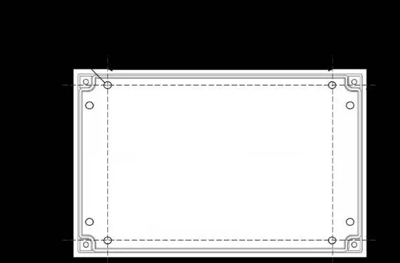

- Placement: Mount the panel 48-60 inches above the finished floor level.
- Mounting: Remove the front cover by unscrewing the four corner bolts using the provided socket wrench. Mark the four screw holes on the wall, ensuring the surface is flat to prevent base distortion.
- Finishing: After connections are made, replace the cover and insert security caps over the bolts.
- Flush Mount: A flush mount kit (bracket and decorative strip) is available from your supplier.
Wiring and Connections
All Class 2 wiring must be installed within flexible tubing to maintain circuit segregation. Wiring of different circuits must be separated by routing, clamping, or barriers.
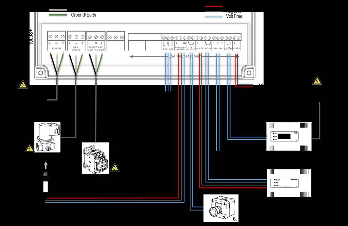
- Power/Line In: 110-120V AC, fused at 3A.
- Gas Solenoid Valve: Connect to [VALVE OUT] using a 3-core cable. The pressure sensor must be screwed into the downstream port of the valve.
- Electric Contactor: Connect to [ELECTRIC CONTACTOR] using a 3-core cable.
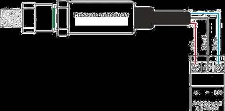
- Pressure Sensor: Wire to [PRESSURE SENSOR] connector. Wiring: Red (+), Black (-), Blue (IN).
- BMS Output: Volt-free connections (NO, COM, NC) for Building Management Systems.
- Gas Detector: Compatible with Merlin LPG, NG, CO, or Hydrogen detectors. If no detector is used, leave the factory-fitted link in place.
- CO2 Monitor: Connect to the CO2 terminal. If not connected, the panel will beep on power-up and the CO2 LED will flash 3 times.
Switch Settings
Settings are configured via switches on the circuit board. Always remove power for 10 seconds after changing settings.
- Auto Reset: OFF (Manual restart required after power loss) or ON (Automatic restart).
- BMS Integration: OFF (Signals gas status) or ON (Signals faults).
- Gas Fill/Prove Time: Adjust fill (5s/10s) and prove (30s/50s) times.
- Auto Shut-Down: Configure [TIME1] and [TIME2] for 2, 4, 8 hours, or disabled.
- Selectable Utility: [ELECTR] switch can be set to ON to turn off electrics during auto-shut down.
Operation
To start the system, turn the key switch to the ON position. Gas and Electric LEDs will flash for 10 seconds, during which you must press the relevant service button to activate the utility. After 10 seconds, utility buttons are disabled; you must turn the key off and back on to adjust services.
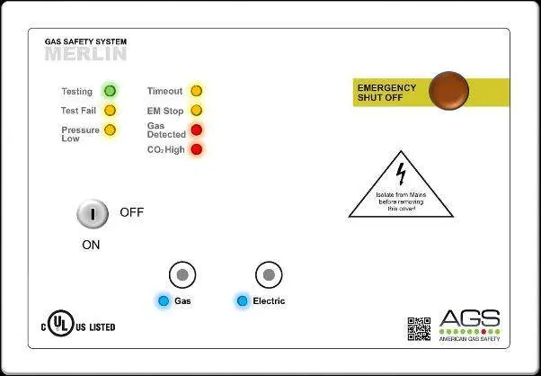
LED Indicators
- Gas: ON when gas is on.
- Electric: ON when electric is on; Flashing when electric is off but enabled.
- Testing: GREEN when the system is checking gas line integrity.
- Test Fail: AMBER if a gas leak is detected on start-up.
- Pressure Low: AMBER if pressure drops below 0.17psi.
- Timeout: AMBER if auto-shut down has occurred.
- EM Stop: AMBER if an emergency shut-off button is activated.
- Gas Detected: RED if an external detector senses gas.
- CO2 High: RED if CO2 concentration reaches alarm levels.
Maintenance
- Cleaning: Regularly remove dust from the enclosure using a slightly damp cloth. Never paint the device or use aerosols near sensors.
- Bump Test: It is recommended to perform regular bump tests to ensure gas detectors are functioning correctly. Contact your AGS representative for suitable testing kits.
General Specifications
- Power Input: 110-120VAC
- Operating Temperature: 32–104°F (0-95%RH Non-Condensing)
- Internal Fuse: 3.15A
- Pressure Sensor Range: 0 - 1.45psi
- Audible Alarm: 65 dB (at 300mm)
Practical help
Common problems
Panel beeps on power up and CO2 LED flashes
The CO2 monitor terminal is disabled. If no monitor is connected, this is normal. If one is connected, check the wiring.
Gas valve will not open
Check if the 'Test Fail' or 'Pressure Low' LEDs are illuminated. Ensure the emergency shut-off button is not activated.
Pressure Low LED is amber
The gas supply pressure has dropped below 0.17psi. Check the gas line for leaks.
Utility buttons do not respond
Utility buttons are only active for 10 seconds after turning the key switch ON. Turn the key OFF and back ON to regain control.
Before use
- Ensure the panel is mounted 48-60 inches above the floor.
- Verify the 3A fuse is installed.
- Ensure the pressure sensor is correctly screwed into the downstream port of the gas valve.
- Check that all wiring is separated and secured.
- Verify that the emergency shut-off button is accessible and not pressed.
- If using a gas detector, ensure it is properly connected and the factory link is removed.
Specs in practice
- Operating Temperature
- 32–104°F (0-95%RH Non-Condensing).
- Internal Fuse
- 3.15A.
- Pressure Sensor Range
- 0 - 1.45psi.
- Audible Alarm
- 65 dB at 300mm distance.
Images and diagrams
- Wiring Diagram: Illustrates connections for Power, Gas Solenoid Valve, Electric Contactor, BMS, Pressure Sensor, and Gas Detectors.
- Pressure Sensor Wiring: Shows the red (+), black (-), and blue (IN) wire connections to the pressure transducer.
Model compatibility
- Compatible with carbon dioxide, natural gas, carbon monoxide, and LPG sensors.
- Can be integrated with fire alarm systems via the EM REMOTE terminal.

Manual page author
David Miller
Documentation analyst
Organizes user manual content into clear summaries, with attention to model details, product context, and everyday usability.