Industrial / Isolation Controllers
User Manual for AGS Merlin 1000SW+ Isolation Controller
Quick guide for the AGS Merlin 1000SW+ Gas, Electric & Water Isolation Controller. Includes installation, wiring diagrams, operation, LED indicators, and maintenance instructions.
Table of contents
Manual images
Click an image to enlargeQuick Guide
The AGS Merlin 1000SW+ is a gas pressure proving, electric, and water isolation system designed for educational establishments and laboratories. It provides centralized control over gas, electric, and water supplies via a key-switch and touch sensors. Key operational notes include:
- Initial Power-Up: Utilities can only be turned on or off within 10 seconds of turning the key switch. After 10 seconds, buttons are disabled; you must cycle the key switch to adjust settings.
- Safety: The system monitors gas pressure and will shut off the gas valve if pressure drops below 0.17psi.
- Timeout: An automatic shut-down feature can be configured for 2, 4, or 8 hours.
Installation
Installation must be performed by a licensed, insured contractor in accordance with local regulations (e.g., NEC/CEC in North America). The panel is designed for surface mounting, 48-60 inches above the finished floor level.
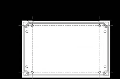
- Remove the front cover using the provided socket wrench.
- Mark and drill four screw holes on the wall.
- Ensure the wall surface is flat to prevent base distortion.
- After wiring, replace the cover and insert security caps over the bolts.
Circuit Board Connections
The circuit board provides terminals for:
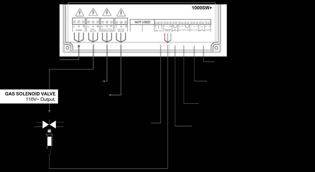
- Power/Line In: 110-120V AC supply, fused at 3A.
- Outputs: Connections for Gas Solenoid Valve, Electric Contactor, and Water Valve (all 110-120V AC).
- BMS Out: Dry contact connections (NO/COM/NC) for Building Management Systems.
- Pressure Sensor: Connects to the downstream port of the gas solenoid valve (Red +, Black -, Blue IN).
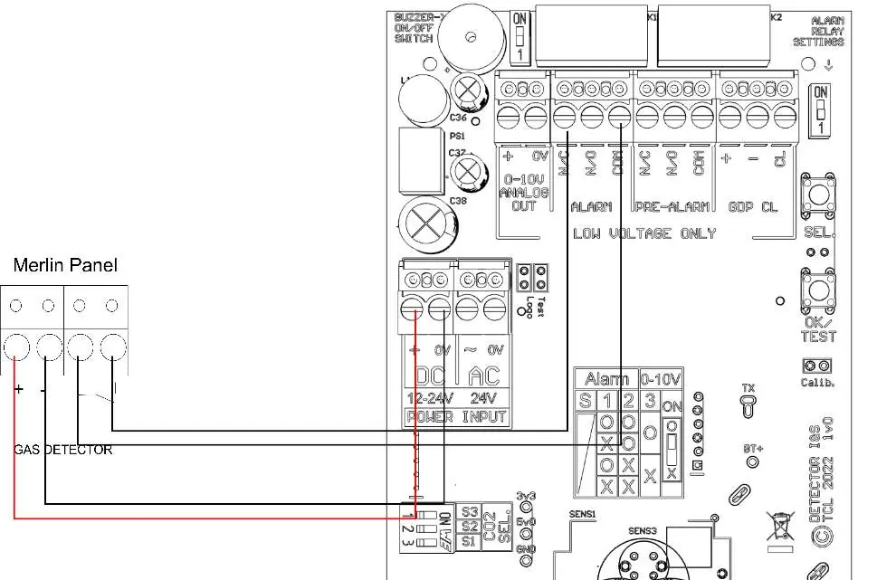
- Gas Detectors: Connects to the panel; if no detector is used, the factory-fitted link must remain.
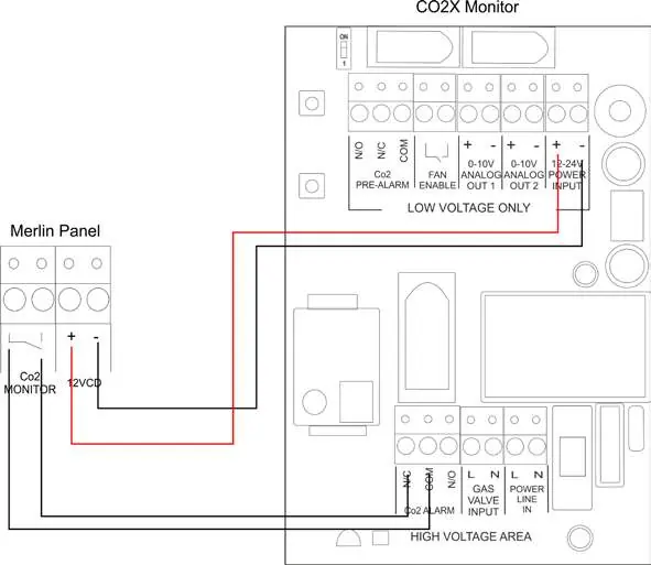
- CO2 Monitor & 12VDC: Power output for external devices (max 50mA).
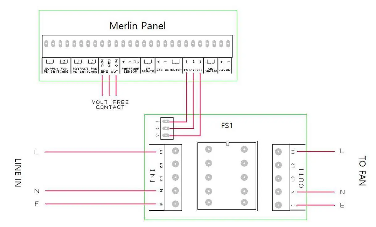
- Fan Switches: Connections for external fan switches (supplied separately).
Operation
The front panel features LED indicators to show system status:
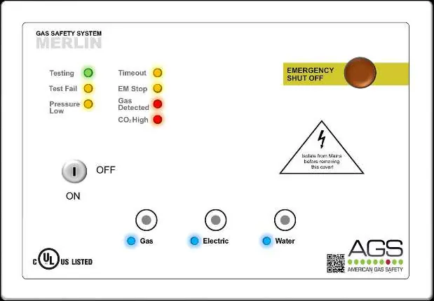
- Gas: Illuminates when gas is on.
- Electric/Water: Illuminates when the respective service is on.
- Testing: Illuminates green during the 30-second gas integrity check.
- Test Fail: Illuminates amber if a gas leak is detected on start-up.
- Pressure Low: Illuminates amber if gas pressure drops below 0.17psi.
- Timeout: Illuminates amber when the auto-shut down timer activates.
- EM Stop: Illuminates amber when an emergency shut-off button is pressed.
- CO2/Gas Detected: Illuminates red if an external detector triggers an alarm.
Maintenance
Keep the panel in good working order by following these guidelines:
- Regularly remove dust from the outer enclosure using a slightly damp cloth.
- Never use detergents, solvents, or aerosols near the device.
- Do not paint the device, as this will seal vents.
- Perform regular 'bump tests' (gas response checks) to ensure detectors are functioning correctly. AGS recommends testing detectors every 12-18 months.
Specifications
The unit operates on 110-120V AC, 50-60Hz, with a maximum power rating of 6W. It is designed for indoor wall mounting with an operating temperature range of -10 to 50°C (14 to 122°F).
Practical help
Common problems
Gas valve closes unexpectedly
Check for gas leaks or low pressure (below 0.17psi). The system will shut off the gas if pressure is insufficient.
Panel beeps on power up
This indicates the CO2 monitor terminal is disabled. Ensure the device is connected or check configuration.
Utility buttons are disabled
Buttons are only active for 10 seconds after turning the key switch. Turn the key off and back on to re-enable.
Before use
- Ensure the wall surface is flat for mounting to prevent base distortion.
- Verify the 110-120V AC power supply is fused at 3A.
- Check that the gas detector is connected or the factory-fitted link is in place.
- Confirm the pressure sensor is correctly wired (Red +, Black -, Blue IN).
- Ensure all cable glands/conduits are separated by at least 20mm.
Specs in practice
- Power Rating
- 6W maximum power consumption.
- Operating Pressure
- 0 - 1.45psi; the gas valve closes if pressure drops below 0.17psi.
- Internal Fuse
- T3.15A L250V.
Images and diagrams
- Wiring diagrams illustrate connections for gas detectors, CO2 monitors, and fan switches.
- Circuit board overview details power input, valve outputs, and BMS relay connections.
Model compatibility
- Compatible with carbon dioxide, natural gas, carbon monoxide, and LPG sensors.
- Designed specifically for use in educational establishments and laboratories.

Manual page author
Emily Carter
User documentation editor
Prepares concise manual descriptions and highlights the most useful setup, operation, and maintenance information for readers.