Industrial / Isolation Controllers
User Manual for AGS Merlin 1000S+i Gas & Electric Isolation Controller
Quick guide for the AGS Merlin 1000S+i Gas & Electric Isolation Controller. Includes installation, wiring diagrams, operation instructions, and maintenance procedures.
Table of contents
Manual images
Click an image to enlargeQuick guide from the manual
The AGS Merlin 1000S+i is a gas and electric isolation system designed for educational establishments and laboratories. It provides teachers with full control over incoming gas supply and bench electrics via a lockable key-switch and touch sensors. The system includes a built-in timeout facility to automatically shut off the gas solenoid valve after a set period (2, 5, or 8 hours).
Installation and Mounting
Installation must be performed by a licensed, insured contractor in accordance with local regulations (NEC/CEC for North America). The panel is designed for surface mounting.
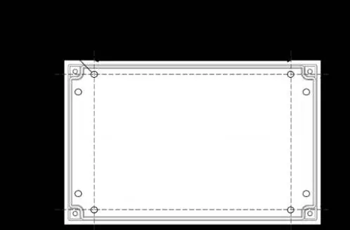

- Place the panel 48-60 inches above the finished floor level.
- Ensure the wall surface is flat to prevent base distortion.
- Remove the front cover using the provided socket wrench to access mounting holes.
- Ensure cable glands/conduits are separated by at least 20mm.
- A flush mount kit is available as an optional accessory.
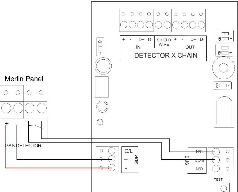
Circuit Board Connections
The circuit board provides terminals for various system components. Ensure all wiring is protected against mechanical damage and isolated from live power sources before opening the cover.

- Power/Line In: 110-120V AC power supply, fused at 3A.
- Gas Solenoid Valve: 110-120V AC output for gas shut-off valve.
- Electric Contactor: 110-120V AC output for bench electrics control.
- BMS Out: Volt-free connections (NO/COM/NC) for Building Management Systems.
- EM Remote/Fire Panel: Connections for remote emergency shut-off buttons or fire alarm integration.
- Gas Detectors: Terminals for connecting gas sensors; use factory-fitted links if no detector is used.
- CO2 Monitor & 12VDC: Power output for CO2 monitors or auxiliary devices (max 50mA).
Switch Settings
The system features several configurable switches on the circuit board:
- Auto Reset: Configures system behavior after power restoration (Manual or Automatic).
- BMS Integration: Sets BMS signaling behavior (Gas status or Fault status).
- Automatic Shut Down Timer: Configures the timeout period (2, 4, 8 hours, or Disabled).
- Utility Shutdown Selection: Configures whether electrics are turned off during auto-shut down.
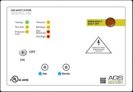
Operation
Upon connecting mains power, the AGS logo LED will illuminate red.
- Turn the key switch to the ON position.
- Gas and Electric LEDs will flash for 10 seconds.
- Press the relevant service button to activate the required utility.
LED Indicators:
- Gas/Electric: Indicates current status of utilities.
- Timeout: Illuminates amber when auto-shut down has occurred.
- EM Stop: Illuminates amber when an emergency shut-off button is pressed.
- CO2/Gas Detected: Illuminates red if gas is detected or CO2 levels reach alarm thresholds.
Maintenance and Bump Testing
Regular maintenance ensures the system remains in good working order.
- Cleaning: Use a slightly damp cloth. Never use detergents, solvents, or aerosols near the device. Do not paint the device.
- Bump Testing: Perform regular gas response checks (bump tests) to ensure detectors are functioning correctly. We recommend testing every 12-18 months.
- Service: If the system fails to operate in an alarm state, do not use it until a full inspection is conducted.
Technical Specifications
- Power Rating: 6W max.
- Voltage Rating: 100-120V AC, 50-60Hz.
- Operating Temperature: -10 to 50°C (14 to 122°F).
- Internal Fuse: T3.15A L250V.
- Dimensions: 7.08 x 10.03 x 3 inches (180 x 255 x 77 mm).
Practical help
Common problems
Panel beeps on power up
The CO2 monitor or external device is not connected; the terminal has been disabled.
Gas valve shuts off unexpectedly
The timeout feature has activated or gas has been detected.
Utility buttons are disabled
Services can only be toggled within 10 seconds of turning the key switch. Turn the key off and back on to adjust.
Before use
- Ensure wall surface is flat for mounting.
- Verify power supply is 110-120V AC.
- Check that all wiring is protected against mechanical damage.
- Ensure gas solenoid valve is connected to the correct output.
- Confirm all detectors are properly wired or factory links are in place.
Specs in practice
- Power Rating
- 6W maximum power consumption.
- Voltage Rating
- 100-120V AC, 50-60Hz input.
- Operating Temperature
- -10 to 50°C (14 to 122°F).
- Internal Fuse
- T3.15A L250V protection.
Images and diagrams
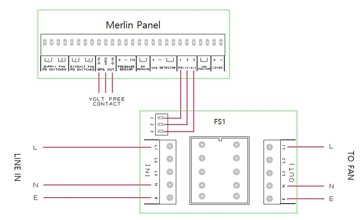
- Wiring diagrams show connections for gas detectors, fan switches, and CO2 monitors.
- Circuit board overview identifies terminals for power, valves, and BMS.
Model compatibility
- Compatible with carbon dioxide, natural gas, carbon monoxide, and LPG sensors.
- Requires licensed, insured contractor for installation.

Manual page author
Michael Turner
Technical manual editor
Reviews PDF manuals for structure, safety notes, and practical product details so readers can find the right information quickly.