Smart Home / Hubs & Controllers
Niko Home Control Connected Control Unit 550-00004 User Manual
Quick guide for the Niko Home Control Connected Control Unit 550-00004. Learn about installation, wiring, technical specifications, and system setup for your smart home controller.
Table of contents
Manual images
Click an image to enlargeQuick guide from the manual
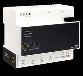
The Niko Home Control Connected Control Unit (550-00004) is the central module for every Niko Home Control 1.x installation. It manages the system logic, powers the bus, connects IP equipment (such as touchscreens and video door stations), and enables remote control via smartphone or tablet. Each installation requires exactly one connected control unit.
Product description
The module is designed for DIN rail mounting and serves as the gateway between your home network and the Niko Home Control system. It features a WAN port for internet connectivity and three RJ45 ports for the internal Niko Home Control network.
Installation and wiring
The unit must be installed on a DIN rail. The wiring configuration is as follows:
- WAN Port: Connect this port to your home network router. The router will assign an IP address to the control unit, enabling communication with Niko Home Control software and remote access.
- RJ45 Ports: Use the three available RJ45 ports to connect IP equipment, such as touchscreens, video door stations, or Ethernet switches that group these devices.
- Power Supply: The unit requires a 230 Vac, 50 Hz power supply.
- Bus Connection: The unit powers the bus, modules, and controls. It includes automatic terminals on the top for connecting to the rail coupler and on the bottom for 230 Vac power.
System setup
To enable remote control and access services such as system updates or diagnostics, you must register your installation at https://mynikohomecontrol.niko.eu. The module contains firmware that can only be programmed using version 1.x of the Niko Home Control programming software.
Technical specifications
- Power supply: 230 Vac ± 10 %, 50 Hz
- Output voltage (SEC): 26 Vdc, max. 400 mA (Safety Extra Low Voltage)
- DIN dimensions: 6TE DIN
- Compatibility: Compatible with smart SMA connected inverters
- Marking: CE
Official resources from the manual
Practical help
Common problems
No remote access to the installation
Ensure the unit is registered at https://mynikohomecontrol.niko.eu and that the WAN port is correctly connected to your home router.
Device not communicating with the network
Verify that the home router has assigned an IP address to the connected control unit via the WAN port.
Before use
- Ensure the unit is mounted on a DIN rail.
- Verify the power supply is 230 Vac, 50 Hz.
- Connect the WAN port to your home network router.
- Connect IP devices (touchscreens, video stations) to the three RJ45 ports.
- Register the installation online for remote access features.
Specs in practice
- 26 Vdc, 400 mA
- The output voltage and maximum current provided by the unit to power the Niko Home Control bus and connected modules.
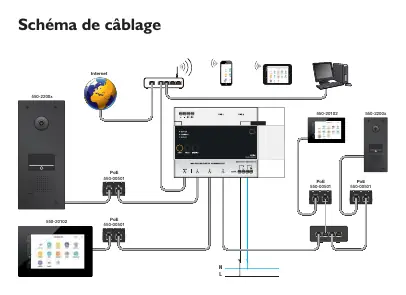
Images and diagrams
- The wiring diagram illustrates the connection of the WAN port to the internet router.
- The diagram shows how to connect PoE switches and IP devices (touchscreens, video stations) to the three RJ45 ports.
Model compatibility
- Compatible with Niko Home Control 1.x programming software only.
- Compatible with smart SMA connected inverters.

Manual page author
Emily Carter
User documentation editor
Prepares concise manual descriptions and highlights the most useful setup, operation, and maintenance information for readers.