Lighting / Work Lights
Nilight 14AWG LED Light Bar Wiring Harness Installation Guide
Quick installation guide for the Nilight 14AWG LED light bar wiring harness. Includes step-by-step wiring instructions, 5-pin rocker switch connection methods, and safety precautions for 12V DC automotive lighting systems.
Table of contents
Manual images
Click an image to enlargeQuick guide from the manual
This guide covers the installation of the Nilight LED light bar wiring harness. It is designed for 12V DC systems. Ensure your light bar wattage does not exceed the harness capacity (300W for 14AWG, 450W for 12AWG). Always tape off unused wire connections to prevent short circuits.
Installation steps
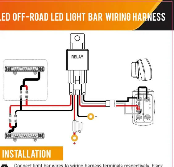
- Connect light bar wires to the harness terminals (black to black, red to red).
- Run the rocker switch wires through the switch cutout in the dashboard.
- Connect the wiring harness to the car battery: red wire (with fuse) to positive, black wire to negative.
- Turn on the power and press the switch to test the light.
5-Pin rocker switch connection
The 5-pin rocker switch allows for different indicator light behaviors. Ensure you tape off any unused wire connections to prevent shorts. The pin-tab outs are as follows: 8 (Upper Light Neg), 2 (Incoming power), 3 (Outgoing to relay), 7 (Lower Light Neg), 6 (Lower Light Pos).
Wiring methods
Choose one of the following methods to complete the switch connection:
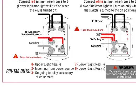
- Wiring Method A: Connect the red jumper wire from pin 2 to 6. The lower indicator light will turn on when the key is turned on.
- Wiring Method B: Connect the white jumper wire from pin 3 to 6. The lower indicator light will turn on only when the switch is turned on.
Technical specifications
- Operating voltage: 12V DC
- 14AWG capacity: Max 300W
- 12AWG capacity: Max 450W
Safety precautions
Strictly follow instructions to avoid hazards. If you are not comfortable with the installation, consult a professional. Ensure all exposed wires are wrapped with electrical insulating tape.
Manufacturer information
Nilight
Practical help
Common problems
Short circuit risk
Ensure all exposed wires are securely wrapped with electrical insulating tape.
Indicator light behavior
Choose between Wiring Method A (light on with key) or Method B (light on with switch) by adjusting jumper wire placement.
Before use
- Verify the system is 12V DC.
- Check if your light bar wattage is within the harness limit (300W for 14AWG, 450W for 12AWG).
- Ensure you have electrical insulating tape for unused connections.
Images and diagrams
- Wiring Method A: Connect red jumper wire from pin 2 to 6 for indicator light on with key.
- Wiring Method B: Connect white jumper wire from pin 3 to 6 for indicator light on with switch.
- Pin-tab outs: 8 (Upper Light Neg), 2 (Incoming power), 3 (Outgoing to relay), 7 (Lower Light Neg), 6 (Lower Light Pos).
Model compatibility
- Designed for 12V DC systems only.

Manual page author
Michael Turner
Technical manual editor
Reviews PDF manuals for structure, safety notes, and practical product details so readers can find the right information quickly.