HVAC / Air Conditioners
Installation Guide for OutEquip Glacier Pro 12V/110V Rooftop Air Conditioner
Comprehensive installation guide for the OutEquip Glacier Pro 12V/110V rooftop air conditioner. Includes detailed instructions on roof opening preparation, gasket installation, power cable routing, mounting procedures, and wiring diagrams.
Table of contents
Manual images
Click an image to enlargeQuick Guide from the Manual
This guide provides essential installation steps for the OutEquip Glacier Pro rooftop air conditioner. Ensure all work is performed by qualified personnel. Always disconnect the RV battery or power source before beginning installation to prevent electrical shock. Use only hand tools or low-torque power tools to avoid damaging components.
Safety Instructions
Follow these guidelines to ensure safe installation and operation:
- Qualified Personnel: Installation and repairs must be performed by individuals with proper mechanical and electrical knowledge.
- Power Safety: Disconnect the RV's battery and power source before starting.
- Environmental Limits: Do not use the unit when ambient temperature is below 40°F to prevent internal frost.
- Compliance: Installation must comply with local codes, including NFPA 1192, NFPA 70 (U.S.), C22.1, and CSA Z240 (Canada).
- Sealant: Use only RV-approved, UV-resistant sealants compatible with your roof material.
Outdoor Unit Footprint & Clearance
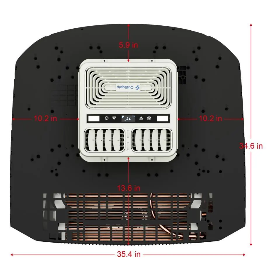
The outdoor unit measures 35.4 x 34.6 inches (900 x 880mm) with a height of 7.1 inches (180mm). Ensure sufficient clearance from the central air duct area to the edges: 5.9 inches (front), 13.6 inches (rear), and 10.2 inches (left and right sides). Measure your rooftop space before installation to avoid interference with solar panels or roof racks.
Roof Opening Requirements
The roof opening must be between 14.1 x 13.7 inches (360 x 350 mm) and 28.7 x 22.8 inches (730 x 580 mm). The surface must be flat, level, and structurally sound. Maintain at least 2–3 inches of clearance from other rooftop components.
Installation Steps
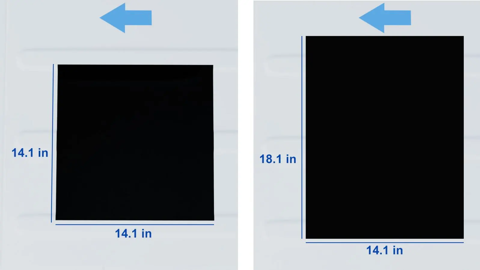
1. Prepare the Opening: Choose between using an existing 14.1 x 14.1 inch opening (requires drilling) or creating an 18.1 x 14.1 inch opening (recommended for easier installation).

2. Install Gasket & Sealant: Apply the EPDM foam gasket around the roof opening. For ribbed roofs, notch the gasket to match contours. Insert support columns into pre-punched holes. Apply UV-resistant sealant around the outer edge and allow it to cure.
3. Position the Unit: Place the rooftop unit onto the gasket. Ensure the chassis drainage cutout remains outside the gasket and that threaded rod holes (#7, #8) are positioned inside the gasket area.
4. Route Power Cable: Either drill a separate hole with a cable gland or cut a small notch in the gasket to route the cable through the main opening.
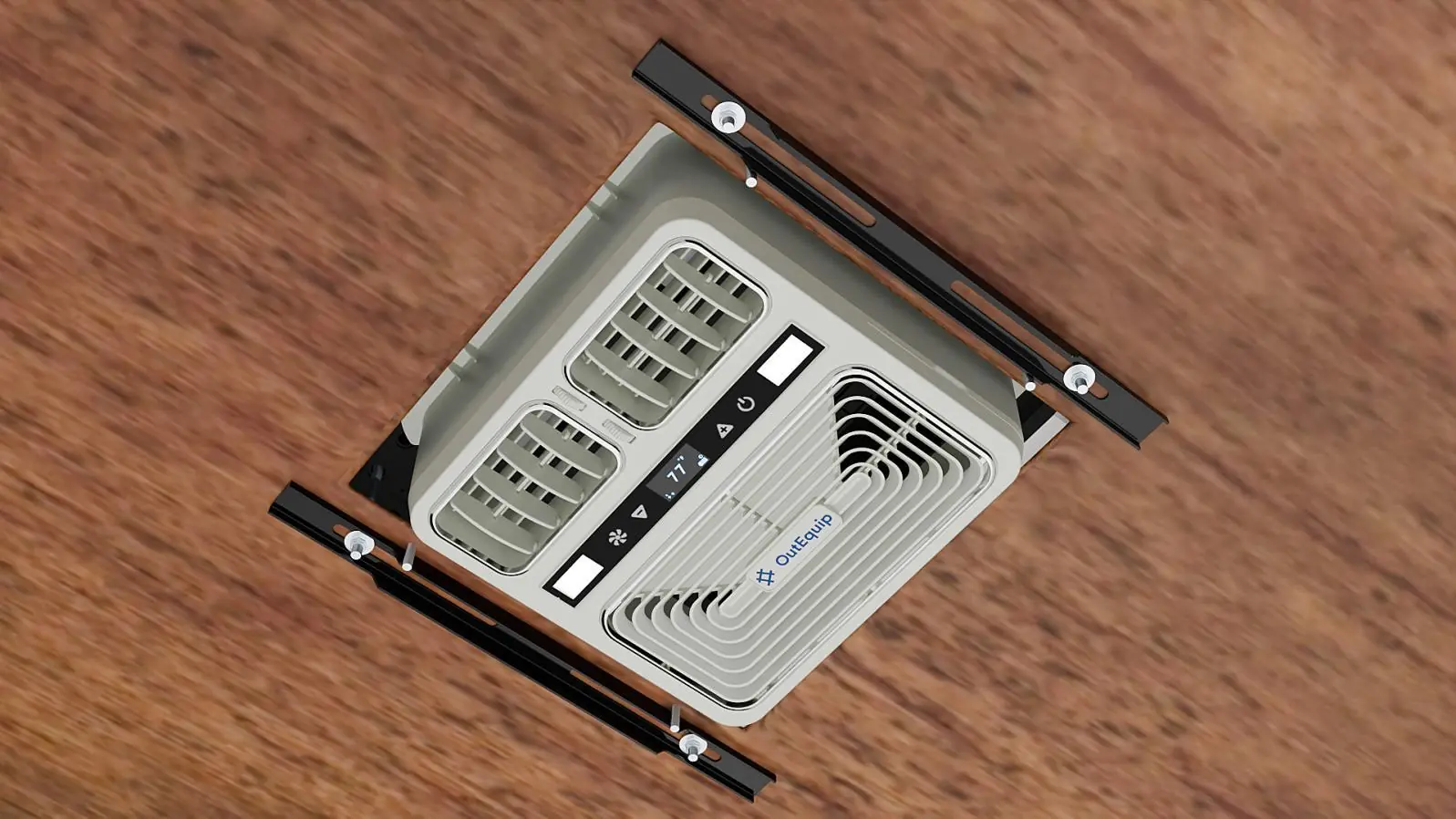
5. Secure the Unit: From inside the vehicle, insert M8 threaded rods into the #8 holes. Hand-tighten nuts, position mounting brackets, and secure with washers and anti-slip nuts. Tighten to a torque of 4.5–5.6 Nm (3.3–4.2 lb-ft).
6. Install Decor Trim: Align the interior trim with the M6 threaded rods inserted through the #6 holes. Tighten nuts evenly until the trim is flush against the ceiling.
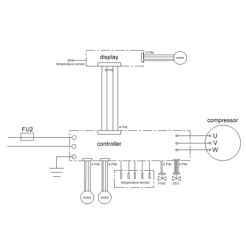
Wiring Diagrams
The manual includes specific field wiring diagrams for 110V AC and 12V AC configurations (with or without heat pump). Ensure all wires are secured away from sharp edges or moving parts.
Warranty
The unit is covered by a 1-Year Limited Warranty from the date of purchase. This covers defective parts or workmanship under normal use. To file a claim, contact [email protected] with your order number and a description of the issue.
Practical help
Common problems
Water leaks
Ensure proper sealing with UV-resistant sealant and correct gasket installation around the roof opening.
Unit not secure
Ensure M8 threaded rods are tightened to the specified torque of 4.5-5.6 Nm.
Frost inside unit
Do not operate the unit when the ambient temperature is lower than 40°F.
Before use
- Verify roof structure can support the unit's weight
- Measure rooftop space for clearance requirements
- Ensure power source is compatible (DC system)
- Gather required tools (hand tools or low-torque power tools)
- Check local electrical codes (NFPA/CSA)
Specs in practice
- Roof Opening
- 14.1 x 13.7 inches (min) to 28.7 x 22.8 inches (max)
- Mounting Torque
- 4.5-5.6 Nm (3.3-4.2 lb-ft) for M8 threaded rods
- Operating Temp
- Do not use below 40°F
Images and diagrams
- Wiring diagrams provided for 110V AC and 12V AC configurations.
- Mounting hole templates for M6 and M8 hardware are included in the package.
Model compatibility
- Designed for use with a DC power system.
- Must comply with NFPA 1192, NFPA 70, C22.1, and CSA Z240 codes.

Manual page author
David Miller
Documentation analyst
Organizes user manual content into clear summaries, with attention to model details, product context, and everyday usability.