HVAC / Air Conditioners
Installation Guide for OutEquip Summit 2 Rooftop Air Conditioner
A comprehensive installation guide for the OutEquip Summit 2 12V/24V rooftop air conditioner. This manual covers safety guidelines, roof opening requirements, gasket installation, power cable routing, mounting procedures, and wiring...
Table of contents
Manual images
Click an image to enlargeQuick Installation Guide
This guide provides essential steps for installing the OutEquip Summit 2 rooftop air conditioner. Ensure all safety protocols are followed and the unit is installed by qualified personnel.
- Safety First: Always disconnect the RV battery or power source before starting. Use proper tools and protective gear.
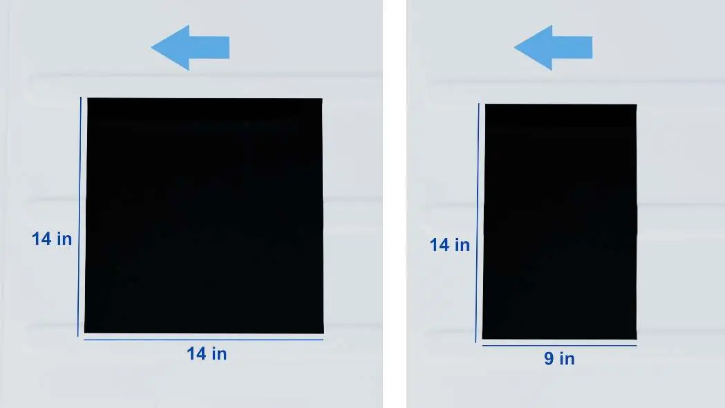
- Roof Prep: Verify the roof opening (14x9 to 16.5x15.7 inches) and ensure the surface is flat and level.
- Sealing: Use the included EPDM foam gasket and UV-resistant sealant to prevent leaks.
- Mounting: Secure the unit from inside using the provided brackets and threaded rods, tightening to 4.5-5.6 Nm.
- Wiring: Route the power cable carefully and connect according to the provided wiring diagram.
Safety Instructions
To ensure safe installation and operation, follow these guidelines:
- Installation must be performed by qualified personnel with mechanical and electrical knowledge.
- Disconnect the RV's battery and power source before beginning installation to avoid electrical shock or fire.
- Do not use the unit in or near flammable environments.
- Do not use the unit when ambient temperature is below 40°F to prevent frost.
- Do not power wash the unit or use detergents for cleaning.
- Ensure compliance with local codes (e.g., NFPA 1192, NFPA 70, C22.1, CSA Z240).
Preparation and Roof Requirements
Before installation, evaluate the available roof space and structural integrity.
- Outdoor Unit Footprint: 28.3 x 28.3 inches (720 x 720mm).
- Roof Opening: Recommended cutout range is 14 x 9 inches (355 x 230 mm) to 16.5 x 15.7 inches (420 x 400 mm).
- Surface: The roof must be flat, level, and strong enough to support the unit's weight (approx. 45 lbs).
- Clearance: Maintain at least 2-3 inches of clearance from other rooftop components like solar panels or antennae.
Installation Steps
Follow these steps to install the unit:
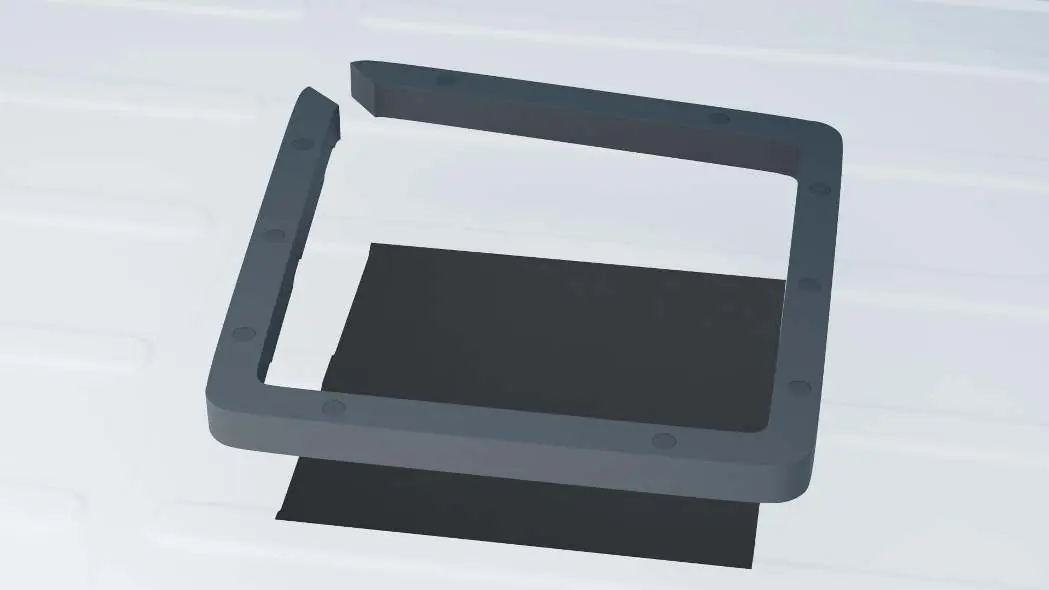
- Install Gasket: Clean the roof area. Stretch and cut the EPDM foam gasket to fit the opening. Apply it to the roof surface. For ribbed roofs, notch the gasket to match contours. Insert support columns into pre-punched holes.
- Seal the Gasket: Apply a continuous bead of UV-resistant RV sealant around the outer edge of the gasket. Smooth with a gloved finger. Allow 24-48 hours to cure before exposure to rain.
- Install Rear Support Foam Blocks: Place hard foam blocks under both rear corners to support the chassis and ensure leveling.
- Position the Outdoor Unit: Place the unit onto the gasket. Ensure the chassis drainage cutout remains outside the gasket.
Power Cable Routing
Choose one of three methods to route the power cable inside:
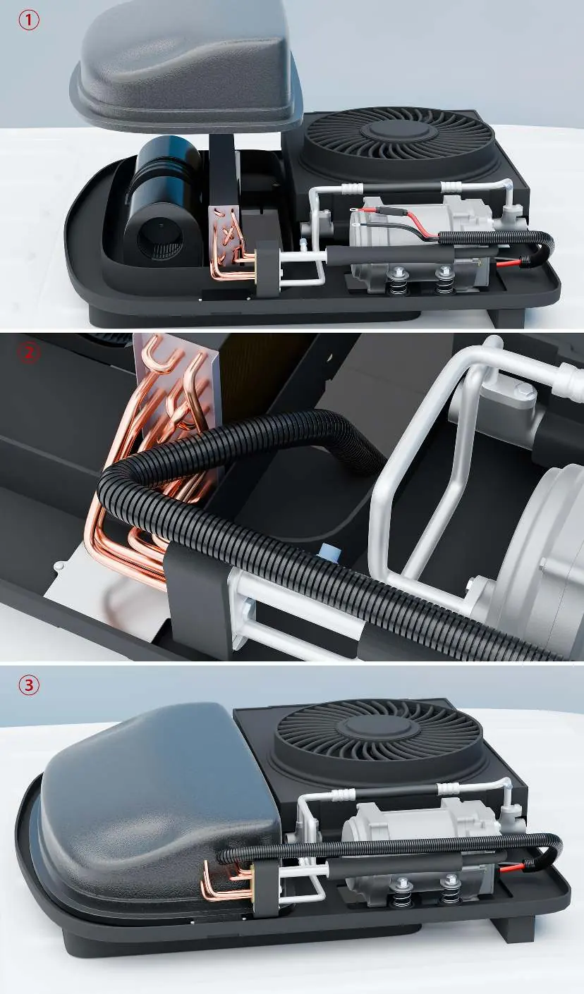
- Option 1: Separate Roof Opening: Drill a hole near the mounting area and use a cable gland or rubber grommet.
- Option 2: Through Return Air Duct: Run the cable through the return duct and existing roof opening.
- Option 3: Notch the Gasket: Cut a small notch in the gasket corner, route the wire under the gasket, and into the main opening.
Securing the Unit
Secure the unit from inside the vehicle:
- Place brackets across the roof opening, aligned with mounting holes.
- Ensure bracket ends rest on solid roof structure with at least 30mm contact.
- Insert threaded rods upward into the rooftop unit (5-14 mm thread engagement).
- Secure brackets using provided washers and anti-slip nuts.
- Tighten to a torque of 4.5-5.6 Nm (3.3-4.2 lb-ft).
- Trim rods if necessary.
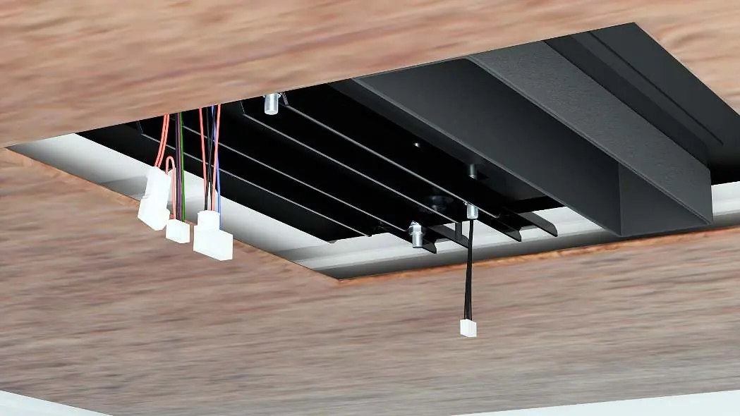
Indoor Panel Installation
Finish the installation by attaching the indoor panel:
- Place panel trim between the ceiling and indoor panel.
- Push upward until ducts connect and form a sealed air path.
- Plug in the wiring harness (connectors are keyed).
- Fasten the panel to the rooftop unit using the included screws. Tighten evenly.
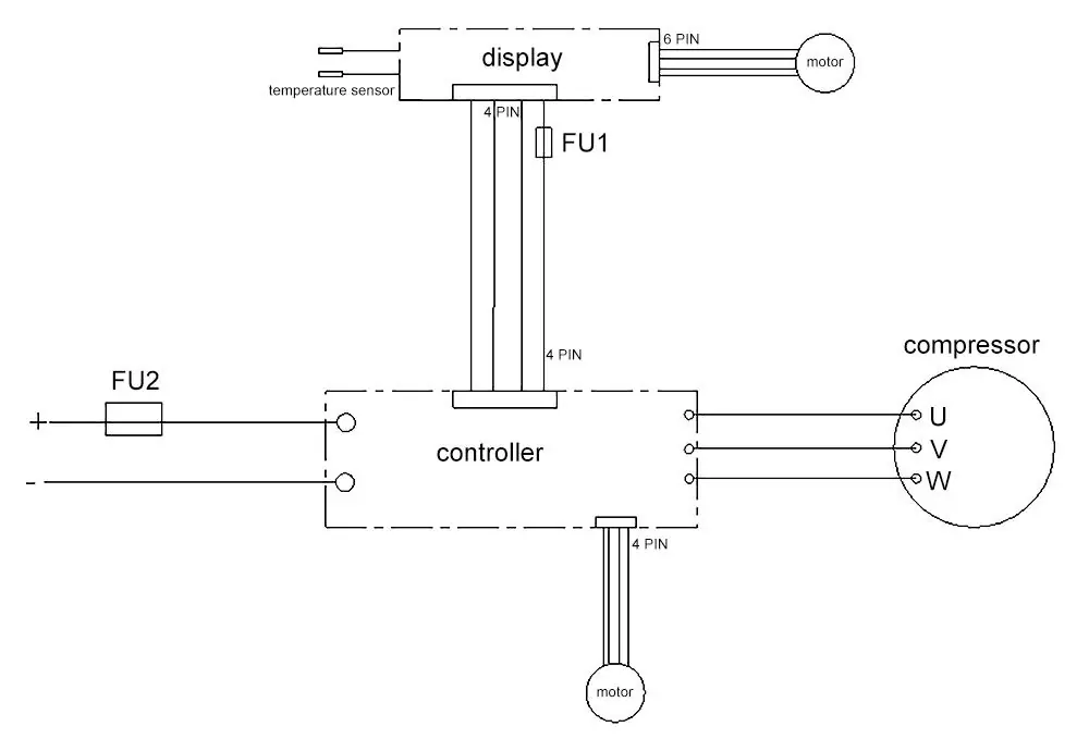
Wiring Diagram
Refer to the unit's field wiring diagram for specific connections. The diagram details the display, controller, compressor, and motor connections, with specific variations for units with or without a heater.
Warranty Information
The unit is covered by a 1-Year Limited Warranty from the date of purchase. This covers defective parts or workmanship. To file a claim, contact [email protected] with your order number and a description of the issue, including photos or video.
Practical help
Common problems
Water leaks
Ensure proper gasket installation and use UV-resistant sealant around the outer edge.
Reduced cooling efficiency
Seal gaps between the roof and interior ceiling using foam strips to prevent warm air recirculation.
Drainage issues
Ensure the chassis drainage cutout remains outside the gasket.
Before use
- Verify roof cutout size (14x9 to 16.5x15.7 inches).
- Ensure roof surface is flat, level, and structurally sound.
- Disconnect RV battery or power source.
- Check for interference with solar panels or roof racks.
- Have UV-resistant RV sealant ready.
- Use a bubble level to check alignment.
Specs in practice
- Overall Size
- 28.3 x 28.3 inches (720 x 720mm)
- Mounting Torque
- 4.5 - 5.6 Nm (3.3 - 4.2 lb-ft)
- Power Cable Sleeve
- 1.18 inches (30 mm) outer diameter
Images and diagrams
- Wiring Diagram: Illustrates connections for the display, controller, compressor, and motor, with distinct configurations for units with and without heaters.
Model compatibility
- Designed for DC power systems only.
- Roof slope up to 15 degrees is acceptable for operation.

Manual page author
David Miller
Documentation analyst
Organizes user manual content into clear summaries, with attention to model details, product context, and everyday usability.