Lighting / Fixtures
Installation Guide for Premium Quality Lighting LED Linear High Bay
Quick installation guide for the Premium Quality Lighting LED Linear High Bay. Includes wiring diagrams, mounting options (chain, cable, pendent), and safety precautions.
Table of contents
Manual images
Click an image to enlargeQuick guide from the manual
This document provides installation instructions for the LED Linear High Bay fixture. Important: Installation, service, and maintenance must be performed by a qualified licensed electrician. Always disconnect electrical power at the fuse or circuit breaker box before beginning any work.
Safety and Warnings
- Risk of Fire or Electrical Shock: Ensure supply voltage matches the luminaire label information. All electrical and grounded connections must comply with the National Electrical Code and local requirements.
- Risk of Injury: Avoid direct eye exposure to the light source while it is on. Keep small parts away from children.
- Environment: Suitable for dry or damp locations.
- Wiring: Do not expose wiring to sharp edges. Use only UL-listed wiring.
Installation
Before installation, remove the fixture from packaging and inspect for damages. Handle with care.
Standard Chain Mount
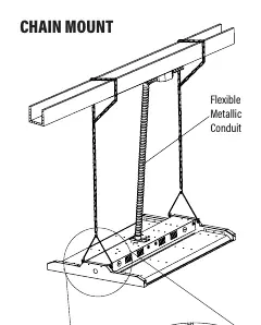
- Install the chain into the provided wire hanger.
- Secure the other end of the chain to a structure rated for the load.
- Install the wire hanger on the side of the top LED channel, ensuring it is fully engaged into the side holes.
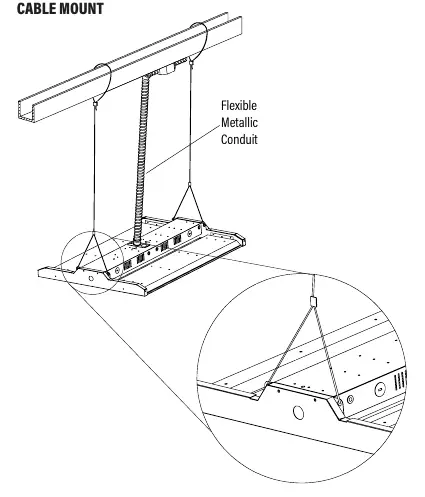
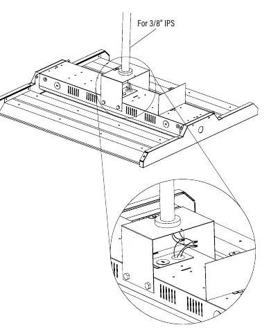
Additional Mounting Options
The fixture supports Cable Mount and Pendent Mount configurations. These mounting accessories are sold separately. Ensure all hanging hardware is double-checked before completing the installation.
Wiring Instructions
Connect the LED high bay wiring to the line voltage wire:
- Black: Hot
- White: Neutral
- Green: Ground
Dimming Connections: The fixture includes purple and pink (or gray) wires for 0-10V low voltage dimming. If not connecting to a 0-10V dimming circuit, ensure these dimmer leads are capped off separately from each other to prevent improper operation and voiding the warranty.
Maintenance
Clean all residues and fingerprints from the new LED high bay and lens after installation.
Practical help
Common problems
Improper fixture operation or voided warranty
Ensure 0-10V dimming leads (purple and pink/gray) are capped off separately if not connected to a dimming circuit.
Risk of electrical shock or fire
Verify supply voltage matches luminaire label and ensure all connections are made in accordance with the National Electrical Code.
Before use
- Disconnect electrical power at the circuit breaker.
- Verify supply voltage matches the luminaire label.
- Ensure the mounting structure is rated for the fixture load.
- Confirm all wiring connections are capped with UL-approved wire connectors.
- Check that all hanging hardware is fully engaged.
Images and diagrams
- The wiring diagram illustrates the connection of line voltage (Black/White/Green) and the dimming control wires (Purple/Pink/Gray) to the LED driver.
Model compatibility
- Suitable for dry or damp locations.
- Dimming wires are 0-10V IEC compliant.

Manual page author
Michael Turner
Technical manual editor
Reviews PDF manuals for structure, safety notes, and practical product details so readers can find the right information quickly.