Electronics / Speaker Accessories
User Manual for RCF SUB 15-AS and SUB 18-AS Professional Subwoofers
Quick guide for RCF SUB 15-AS and SUB 18-AS active subwoofers. Includes setup instructions, rear panel controls, connection diagrams, troubleshooting, and technical specifications.
Table of contents
Quick guide from the manual
The RCF SUB 15-AS and SUB 18-AS are high-power active subwoofers designed for live sound applications. Before connecting the device, verify the voltage label on the rear panel (115V or 230V). Always ensure the volume control is set to the minimum level before turning the system on. It is recommended to turn the mixer on first, then the subwoofer, and turn the subwoofer off immediately after use. For suspended installations, use only dedicated anchoring points and consult a professional installer.
Rear panel features and controls
The rear panel provides the following controls and connections:
- Line In Combo XLR-Jack Inputs: Accepts balanced or unbalanced line-level signals.
- Link Out Male XLR Signal Output: Provides a loop-through for daisy-chaining speakers.
- Xover Male XLR Signal Output: Provides a signal through with an internal high-pass filter set to 80Hz.
- Sig/Clip LED: Indicates signal presence (green) or overload (red). If the clip LED blinks frequently or stays red, reduce the signal level.
- Volume Control: Adjusts the master volume.
- Sub Polarity Button: Reverses the polarity of the signal sent to the woofer (indicated by the yellow Reverse LED).
- Sub Low Pass Button: Sets the low-pass filter frequency. Options are 80Hz or 100Hz (indicated by LEDs). If both LEDs are off, the frequency is set to 400Hz.
- Power Main Switch: Turns the AC power on and off.
Connections
The connectors must be wired according to AES standards:
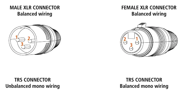
- Male/Female XLR: Pin 1 = Ground (Shield), Pin 2 = Hot (+), Pin 3 = Cold (-).
- TRS Connector (Balanced): Tip = Hot (+), Ring = Cold (-), Sleeve = Ground (Shield).
- TRS Connector (Unbalanced): Tip = Hot (+), Sleeve = Ground (Shield).
Care and maintenance
To ensure long-life service:
- If used outdoors, ensure the unit is under cover and protected from rain and moisture.
- In cold environments, warm up the voice coils by sending a low-level signal for about 15 minutes before applying high-power signals.
- Clean exterior surfaces only with a dry cloth when the power is turned off. Do not use solvents or abrasives.
Troubleshooting
If you encounter issues, check the following:
- Speaker doesn't turn on: Ensure it is connected to active AC power and the switch is on.
- No sound: Check signal source and ensure cables are not damaged.
- Distorted sound/Overload LED blinks: Turn down the mixer output level.
- Humming/Buzzing: Check AC grounding and all equipment connected to the mixer input.
Practical help
Common problems
Speaker does not turn on
Verify the power cable is intact and connected to an active AC power source.
No sound output
Check if the signal source is sending correctly and inspect signal cables for damage.
Distorted sound and Overload LED blinks frequently
Turn down the output level of the mixer.
Humming or buzzing noise
Check AC grounding and all equipment connected to the mixer input, including cables and connectors.
Before use
- Verify the voltage label on the rear panel (115V or 230V).
- Ensure the volume control is at the minimum level before turning on.
- Ensure the mixer is already ON before turning on the subwoofer.
- Use only screened cables for line signals.
- Avoid placing signal cables near power cables or equipment producing high-intensity electromagnetic fields.
Specs in practice
- Frequency Response
- The range of frequencies the subwoofer can reproduce (35Hz-400Hz for 15-AS, 20Hz-400Hz for 18-AS).
- Low Pass Filter
- Adjustable crossover frequency (80Hz, 100Hz, or 400Hz) to filter the signal fed to the woofer.
Images and diagrams
- Rear Panel: Shows the layout of inputs, outputs, volume, polarity, and low-pass filter controls.
- XLR Wiring: Details the pinout for balanced XLR connections (Pin 1 Ground, Pin 2 Hot, Pin 3 Cold).
- TRS Wiring: Details the pinout for balanced and unbalanced TRS connections.
Model compatibility
- Compatible with 10, 12, or 15-inch loudspeakers.
- Suspended installation requires professional qualified installers and dedicated anchoring points.

Manual page author
Emily Carter
User documentation editor
Prepares concise manual descriptions and highlights the most useful setup, operation, and maintenance information for readers.