Electronics / Speakers & Soundbars
Owner Manual for RCF ST 12-SMA II and ST 15-SMA II Active Stage Monitors
Quick guide for RCF ST 12-SMA II and ST 15-SMA II active stage monitors. Includes setup, connection, safety, troubleshooting, and technical specifications.
Table of contents
Manual images
Click an image to enlargeQuick Guide
This manual provides essential information for the safe and correct operation of the RCF ST 12-SMA II and ST 15-SMA II active stage monitors. Always ensure the volume is at the minimum level before powering on the system. The mixer should be powered on before the speakers to avoid damaging the equipment or producing loud pops. Always turn off the speakers immediately after use.
Product Description
The ST Series is a line of active loudspeakers designed for professional monitoring. They feature high-output transducers, digital amplification, and FIR filtering technology for transparent sound and minimal latency. The cabinets are constructed from Baltic birch plywood with a rugged design suitable for stage use.
Rear Panel Controls
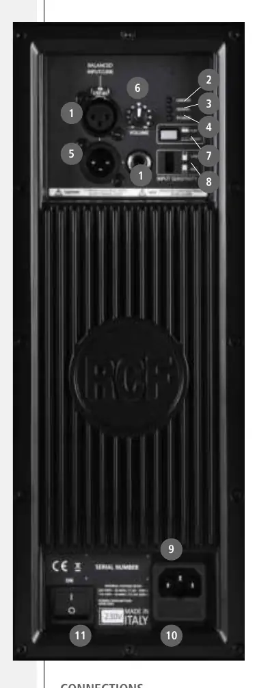
- Jack/Female XLR Inputs: Balanced inputs for microphones or line-level audio sources.
- Limiter LED: Blinks red when the soft clipping circuit is active. Occasional blinking is normal; frequent or continuous blinking indicates the signal level is too high.
- Signal LED: Lights green when a signal is present.
- Power Status LED: Lights green when the speaker is powered on.
- Male XLR Signal Output: Provides a loop-through for daisy-chaining speakers.
- Volume Control: Adjusts the amplifier volume.
- Flat/Boost Switch: Selects equalization. Boost is recommended for music applications on a floor stand; Flat is recommended for monitoring applications.
- Input Sensitivity Switch: Set to LINE for line-level sources (0 dB) or MIC for microphone sources.
- IEC AC Socket: Power cord connection.
- Fuse Carrier: Mains fuse housing.
- Power Main Switch: Turns the unit on and off.
Connections
The XLR connectors follow the AES standard:
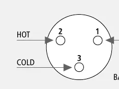
- Pin 1: Ground (Shield)
- Pin 2: Hot (+)
- Pin 3: Cold (-)
Installation
The cabinet features a 35 mm socket on the bottom for mounting on a speaker stand. Warning: Never suspend the speakers by their handles. Handles are designed for transportation only, not for rigging.
Operation
The amplifiers use a microprocessor for DSP and amplifier control. Upon power-up, the system performs an initialization test where the Limiter, Signal, and Power Status LEDs remain off for approximately 2 seconds. Once initialized, the green Power Status LED will remain steadily on.
Troubleshooting
The microprocessor signals failures by flashing the red Limiter LED:
- Warning (1 or 2 flashes): Non-severe error, performance is not limited.
- Limitation (3 or 4 flashes): Error detected, performance is limited (sound level reduced by 3 dB). Contact service.
- Failure (5 to 8 flashes): Severe malfunction, speaker switches to mute.
If a failure occurs, check the power supply, ensure the amplifier is not overheated, and disconnect/reconnect the power. If the red Limiter LED persists, contact an authorized service center.
Technical Specifications
ST 12-SMA II: Frequency response 45-20 kHz, Max SPL 130 dB, 600W RMS / 1200W Peak power.
ST 15-SMA II: Frequency response 45-20 kHz, Max SPL 131 dB, 600W RMS / 1200W Peak power.
Practical help
Common problems
Limiter LED blinks frequently or lights continuously
The signal level is too high; turn down the signal level.
No sound, Ready LED off, Limiter LED flashes
Severe failure detected. Disconnect power, wait a few minutes, and reconnect. If it persists, contact an authorized service center.
Strange odors or smoke
Switch off the unit immediately and disconnect the power cable.
Before use
- Ensure mains voltage matches the rating plate.
- Set volume to minimum before powering on.
- Ensure the mixer is powered on before the speaker.
- Use screened cables for signal connections.
- Ensure adequate air circulation around the unit.
Specs in practice
- Crossover point
- 1.400 Hz.
Images and diagrams
- The rear panel contains all inputs, volume, EQ, and power controls.
- XLR pinout: Pin 1 is Ground, Pin 2 is Hot (+), Pin 3 is Cold (-).
Model compatibility
- Compatible with 35 mm speaker stands.
- Do not suspend by handles.

Manual page author
Michael Turner
Technical manual editor
Reviews PDF manuals for structure, safety notes, and practical product details so readers can find the right information quickly.