Power / Batteries & Chargers
Redarc VI Series 12V to 24V Voltage Booster User Manual
Quick guide for Redarc VI180D, VI360D, and VI720D 12V to 24V voltage boosters. Includes wiring diagrams, installation precautions, and technical specifications.
Table of contents
Manual images
Click an image to enlargeQuick Guide
The Redarc VI Series converters are designed to supply 24VDC from a 12VDC automotive electrical system. These units are fully encapsulated and feature a highly efficient switchmode design. Proper installation, including the use of correct fuses and sound electrical connections, is critical for safe operation.
Connections
The unit features three connecting wires. Ensure these are connected correctly to avoid damage:
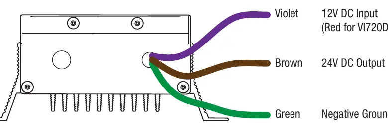
- Violet: 12V DC Input (Red for VI720D)
- Brown: 24V DC Output
- Green: Negative Ground
Installation
For optimal performance and safety, follow these installation guidelines:
- Mount the unit in a cool, sheltered location.
- The unit must be mounted vertically to allow for free airflow.
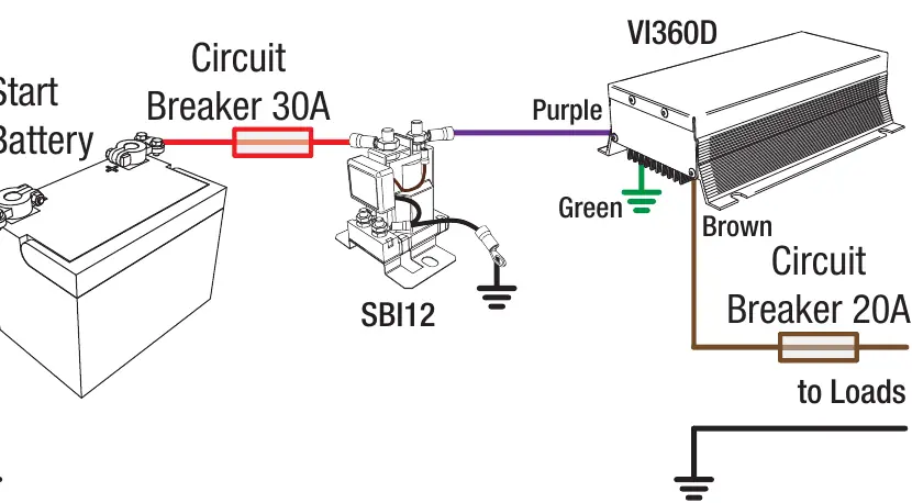
- Use an SBI or an ignition-controlled relay for the 12V input lead connection.
- Install appropriate circuit breakers or fuses as specified in the technical specifications table.
Precautions
- Fuses: Never replace fuses with a higher rating than specified.
- Overloading: Avoid overloading the unit, as this may damage the converter, wiring, or connected systems.
- Cleaning: The internal electronics are potted in silicone; avoid pressure cleaning the unit.
Specifications
The following specifications apply to the VI Series models:
- Supply Range: 12V-15VDC
- Output Voltage: 24VDC
- Conversion Efficiency: >85%
- Ambient Temperature Range: -10°C to +50°C
- Warranty: 2 years
Refer to the table in the manual for model-specific fuse requirements (Input/Output) and dimensions for the VI180D, VI360D, and VI720D.
Warranty
Redarc provides a 2-year warranty against defects in materials and workmanship. For technical support or warranty claims, contact Redarc Electronics Pty Ltd at 23 Brodie Road (North), Lonsdale SA 5160, via email at [email protected], or by phone at +61 8 8322 4848.
Practical help
Common problems
Unit damage or system failure
Avoid overloading the unit and ensure all wiring is rated correctly for the current load.
Overheating
Ensure the unit is mounted in a cool, sheltered location with free airflow and is oriented vertically.
Fuse blowing
Check that the fuse ratings match the specifications for your specific model (VI180D, VI360D, or VI720D). Never use a higher rating fuse.
Before use
- Verify the input voltage is between 12V and 15VDC.
- Ensure the mounting location is cool, sheltered, and allows for vertical mounting.
- Confirm you have the correct fuses for your specific model.
- Ensure an SBI or ignition-controlled relay is used for the 12V input.
- Check that all wire connections (Violet, Brown, Green) are secure.
Specs in practice
- Supply Range
- The acceptable input voltage range from the vehicle's electrical system (12V-15VDC).
- Output Current Rating
- The maximum continuous current the unit can supply at 24V.
- Conversion Efficiency
- The ratio of output power to input power; >85% indicates high efficiency.
Images and diagrams
- The wiring diagram illustrates the connection path from the Start Battery through a circuit breaker and SBI12 to the voltage booster, and finally to the loads.
- Wire color coding: Violet is 12V Input, Brown is 24V Output, and Green is Negative Ground.
Model compatibility
- Designed for 12V automotive electrical systems.
- Not suitable for pressure cleaning due to silicone potting.

Manual page author
Emily Carter
User documentation editor
Prepares concise manual descriptions and highlights the most useful setup, operation, and maintenance information for readers.