Electronics / Security Systems
User Manual for Risco LuNAR 150DTG3 Ceiling Motion Detector
Quick guide for the Risco LuNAR 150DTG3 ceiling motion detector. Includes installation steps, wiring diagrams, jumper settings, LED status indicators, and technical specifications.
Table of contents
Manual images
Click an image to enlargeQuick Guide from the Manual
The LuNAR 150DTG3 is a ceiling-mounted motion detector featuring Anti-Mask and Anti-Cloak (ACT) technologies. Upon power-up, the device enters a 2-3 minute warm-up period where LEDs flash consecutively. After this period, perform a walk test to verify coverage. Ensure the detector cover is securely fitted before applying power. The microwave (MW) range can be adjusted via the potentiometer on the PCB to suit the protected area.
Installation and Maintenance
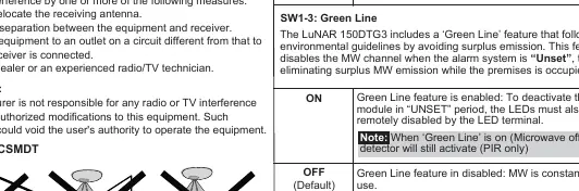
Cover Removal: Hold the base of the detector with one hand and twist the cover clockwise with the other until it stops (see Figure 1).
Knockouts: Use a suitable tool to open the necessary knockouts on the detector base (see Figure 2). If using a back tamper, you must open the tamper back knockout.
Reassembly: Install the front cover in reverse sequence of removal.
Terminal Wiring
Connect the wires to the terminal block as follows (see Figure 3):
- - 12V +: 12VDC Input.
- ALARM: N.C. Relay.
- TAMPER: N.C. Tamper switch.
- FAULT/AM: Normally Closed Relay. Opens on masking detection, self-test failure, or input voltage below 8VDC.
- LED: Remote LED control.
- SET: Remote SET/UNSET control.
Jumper Settings
Configure the jumpers on the PCB to match your control panel requirements (see Figure 4):
- SW1-1 (LED): Enables/disables LED operation.
- SW1-2 (ACT): Enables/disables ACT mode. Do not use in corridors or areas with expected movement outside the protected zone.
- SW1-3 (Green Line): Enables/disables the Green Line feature (disables MW channel when system is Unset).
- SW1-4 (Self Test): Used to test detection technologies (Local or Remote Self Test).
- J1, J2, J3 (EOL): Selects resistance for Tamper, Alarm, and Fault/Anti-Mask circuits (1K, 2.2K, 4.7K, 5.6K, 6.8K, 12K).
Walk Test
Two minutes after applying power, walk test the detector over the entire protected area to verify proper operation. Adjust the MW range potentiometer to the lowest possible setting that provides sufficient coverage for the inner boundary of the protected area.
LED Indicators
- Yellow: PIR detection (On) or PIR channel trouble (Flashing).
- Green: MW detection (On) or MW channel trouble (Flashing).
- Red: Alarm (On) or Fault/Anti-Mask detection (Flashing).
- All LEDs Flashing: Warm-up period.
Technical Specifications
- Voltage: 9-16VDC.
- Current Consumption: 16mA (typical) to 41mA (max) at 12VDC.
- Operating Temperature: -20°C to 55°C (-4°F to 131°F).
- Coverage: 360° field of view with 110° wide angle Fresnel lens.
- Weight: 200g (7 oz).
Practical help
Common problems
LEDs flashing consecutively after power-up
This indicates the 2-3 minute warm-up period. Wait for it to finish.
FAULT/AM relay activates
Check for masking, self-test failure, or input voltage below 8VDC.
Microwave detection issues
Adjust the MW range potentiometer on the PCB to the lowest setting that still covers the required area.
Before use
- Ensure the detector cover is securely fitted before applying power.
- Verify input voltage is between 9-16VDC.
- Configure EOL resistors (J1, J2, J3) according to your control panel requirements.
- Set jumpers (SW1-1 to SW1-4) based on desired functionality.
- Perform a walk test after installation.
Specs in practice
- Current consumption
- 16mA (typical) to 41mA (max) at 12VDC.
- Operating temperature
- -20°C to 55°C (-4°F to 131°F).
- Detection coverage
- 360° field of view with 110° wide angle Fresnel lens.
Images and diagrams
- Figure 1: Shows how to remove the front cover by twisting clockwise.
- Figure 3: Terminal wiring layout for power, alarm, tamper, fault, LED, and SET inputs.
- Figure 4: Schematic for EOL resistors connection.
Model compatibility
- Compatible with Grade 3 installations.
- Anti-Masking detection is operational in 'Unset' mode only.

Manual page author
Emily Carter
User documentation editor
Prepares concise manual descriptions and highlights the most useful setup, operation, and maintenance information for readers.