Home / Electrical Accessories
Saxby Alto Recessed LED Downlight
Installation and wiring guide for Saxby Alto Recessed LED Downlights (models 90957, 90958, 90959). Includes cut-out dimensions, wiring instructions, and safety precautions.
Table of contents
Manual images
Click an image to enlargeQuick guide from the manual
This product must be installed by a competent and qualified electrician in accordance with IEE Wiring Regulations and current Building Regulations. The system operates at Safety Extra Low Voltage via the supplied LED driver and must never be connected directly to the mains. This product is not suitable for dimming.
Installation
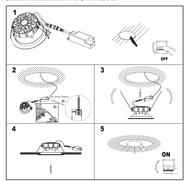
Before installation, ensure the power is switched off at the mains. Plan the layout to ensure cables reach the LED driver and maintain adequate ventilation. The unit must be mounted out of arms reach and at least 100mm from a joist. The distance between units must be at least 0.5m.
Cut-out dimensions:
- 90957: 105mm diameter (Minimum cavity depth: 63mm)
- 90958: 155mm diameter (Minimum cavity depth: 82mm)
- 90959: 205mm diameter (Minimum cavity depth: 102mm)
It is recommended to cut the hole slightly smaller than specified and file it until the unit fits snugly. Position the LED driver near the mains outlet, pull the mains wire through the hole, and connect as detailed in the wiring section. Push the spring clips upwards to fit the unit into the ceiling hole.
Wiring
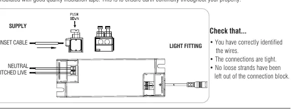
This unit is double insulated and does not require connection to an Earth circuit. If incoming earth cables are present, they must be joined together and well insulated with good quality insulation tape to ensure earth continuity. Ensure connections are tight and no loose strands are left out of the connection block.
Safety and Care
Always disconnect the product from the mains at least 10 minutes before any maintenance or adjustment to allow it to cool down. Clean with a soft dry cloth; do not use solvents or abrasive cleaners. If the unit is damaged, it cannot be serviced and must be scrapped.
Technical Data
Supply Voltage: 220-240 V~, 50 Hz. The light source is non-replaceable. Control gear is replaceable by a professional.
Practical help
Common problems
Product is not suitable for dimming
Do not connect to a dimmer switch.
Unit requires earth connection
This unit is double insulated and does not require an earth connection. If earth cables are present, join and insulate them separately.
Installation difficulty
Ensure the hole is cut slightly smaller than the specified size and file to fit for a snug installation.
Before use
- Ensure power is switched off at the mains
- Verify the correct cut-out size for your model (105mm, 155mm, or 205mm)
- Check that all connections are tight
- Ensure no loose strands are left out of the connection block
- Confirm the unit is at least 100mm from a joist
- Ensure the distance between units is at least 0.5m
Specs in practice
- Supply Voltage
- 220-240 V~, 50 Hz
- 90957 Cut hole
- 105mm diameter, 63mm min depth
- 90958 Cut hole
- 155mm diameter, 82mm min depth
- 90959 Cut hole
- 205mm diameter, 102mm min depth
Images and diagrams
- Wiring diagram shows connection from supply to the LED driver and then to the light fitting.
- Installation steps show the sequence of cutting the hole, wiring, and inserting the unit using spring clips.
Model compatibility
- Not suitable for dimming.
- Must be installed by a qualified electrician.
- Requires supplied LED driver; do not connect directly to mains.

Manual page author
David Miller
Documentation analyst
Organizes user manual content into clear summaries, with attention to model details, product context, and everyday usability.