Automotive / Transmission Systems
Installation Instructions for Transgo 2004R-LU Hydraulic Lock Up Kit
Professional installation guide for the Transgo 2004R-LU Hydraulic Lock Up Kit. Includes detailed steps for valve body boring, governor circuit modification, exhaust port addition, and separator plate conversion.
Quick answers from the manual
Quick answer
- This kit allows you to tune the TCC shift point on 2004R transmissions without electrical requirements by modifying the valve body and separator plate. p. 1
Key actions
- Modify the valve body by boring, adding a governor circuit, and adding an exhaust port. p. 2, 3, 4
- Ream the valve bore using the provided reamer and guide. p. 5
- Convert the separator plate to 'B' style by drilling hole B and plugging hole A. p. 6
Problems and fixes
Shift timing issues
Do not use HO Governor and standard VB. Use matching combinations.
p. 7Technical specifications
| Parameter | Value | Meaning | Pages |
|---|---|---|---|
| HO Governor Max Throttle Shifts | 5000 to 5500 RPM | Shift point for High Output governor and matching VB. | p. 7 |
| Standard Governor Max Throttle Shifts | 4000 to 4600 RPM | Shift point for Standard governor and matching VB. | p. 7 |
Where to find it in the PDF
- Valve Body Boring p. 2
- Governor Circuit Modification p. 3
- Exhaust Port Modification p. 4
- Reaming Valve Bore p. 5
- Separator Plate Modification p. 6
- Governor Identification p. 7
Table of contents
Manual images
Click an image to enlargeQuick Guide
The Transgo 2004R-LU Hydraulic Lock Up Kit is designed for professional use only. It allows for tuning the TCC shift point on 2004R transmissions without requiring electrical modifications. Technical skill level required is HIGH due to the necessity of valve body boring. Ensure you identify your valve body and governor type correctly before starting, as mismatched combinations will cause shift timing issues.
Tools Included
The kit includes the following specialized tools. Keep these for future use:
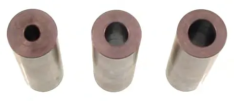
- Small Pilot Guide
- Large Pilot Guide
- Final Reamer Guide
- Reamer
- .201 Drill
- .125 Drill
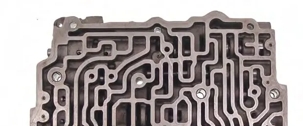
Valve Body Modification
The modification process involves several critical drilling steps:
- Drilling for Valves: Install the small E-clip on the Small Pilot Drill to set depth. Insert the Small Pilot Guide into the valve body (VB). Use low speed, dip the drill in lube, and clean chips frequently. Stop when the E-clip contacts the guide. Repeat with the Large Pilot Guide and Large Pilot Drill.
- Adding Governor Circuit: Use a straight edge to split the difference between the roll pin hole and the bolt hole. Make a center punch at the intersection. Drill straight down slowly with the .125 drill until you break into the bore.
- Adding Exhaust Port: Locate the "RIB" below the flat "pad" area. Center punch the pad above the RIB. Drill a .125 hole at the specified angle to break into the bore at the inboard end.
Reaming Valve Bore
After drilling, the valve bore must be reamed:

- Clean the VB of all debris.
- Lube the reamer cutting edge and insert the shank into the large end of the Final Reamer Guide.
- Insert the assembly into the VB.
- Attach the drill and ream at a slow speed, adding lube, until the reamer bottoms out.
- Clean the VB thoroughly and verify the TCC Shift Valve moves freely in the new bore.
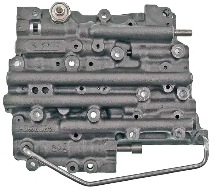
Separator Plate Modification
To use TCC shift valves, you must convert your separator plate to a "B" style plate:
- Drilling: Use the gasket as a guide to drill hole "B" with the .125 drill.
- Plugging Hole A: Enlarge hole "A" with the .201 drill. Use the Large Pilot Drill to chamfer both sides of the hole. Insert the slug into the hole and expand it by tapping with a hammer on both sides. Rub the slug flush on the CASE side using a file or sharpening stone.
Governor Identification
Always match your governor to your valve body:
- High Output (HO) Governor: Matches VB codes BQ, BR, CQ, CZ, TT. Max throttle shifts: 5000-5500 RPM.
- Standard Governor: Matches VB codes OZ, KZ, AA, BY, CR, CT. Max throttle shifts: 4000-4600 RPM.
- Warning: Do not mix HO and Standard components.
Practical help
Common problems
Shift timing issues
Ensure you are not using an HO Governor with a standard Valve Body (or vice versa). Use matching combinations.
Valve sticking
Ensure the valve body is completely clean of debris after reaming and verify the valve moves freely before final assembly.
Before use
- Verify technical skill level is HIGH.
- Ensure you have the correct tools (included in kit).
- Identify your Valve Body (VB) type (HO vs Standard).
- Check if your VB has a Dummy Plug.
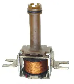
- Verify you have a solenoid with a good O-ring.
Specs in practice
- Standard Governor
- Secondary weight measures .355, max throttle shifts 4000-4600 RPM.
Images and diagrams
- Figure 1 (Page 3): Shows the exact location for the governor circuit modification center punch.
- Figure 2 (Page 4): Shows the location for the exhaust port modification on the valve body.
Model compatibility
- For professional use only.
- Not for use with mismatched HO/Standard governor and VB combinations.
- Plate must have hole 'B' and NOT hole 'A' to use TCC Shift valves.

Manual page author
Michael Turner
Technical manual editor
Reviews PDF manuals for structure, safety notes, and practical product details so readers can find the right information quickly.