Lighting / Fixtures
Instruction Manual for TRIO TS-130S HF Transceiver
Quick guide for the TRIO TS-130S series HF transceiver, covering operation, technical specifications, frequency ranges, and optional accessories.
Table of contents
Manual images
Jump to the sectionQuick guide from the manual
The TRIO TS-130 series is a compact, solid-state HF SSB/CW transceiver designed for mobile and fixed operation. It covers amateur bands from 3.5 to 29.7 MHz. This document provides essential information on operating features, technical specifications, and system integration.
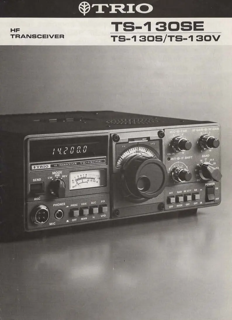
Device Overview
The transceiver features a digital frequency display, IF shift for interference reduction, a built-in speech processor, and a noise blanker. The TS-130SE and TS-130S models are high-power versions, while the TS-130V is a low-power version for QRP operation.
Operating Features
- IF Shift: Allows moving the IF passband to avoid interfering signals.
- Speech Processor: Increases average SSB output power by compressing audio.
- VOX Circuit: Supports push-to-talk and voice-operated transmission with adjustable gain and delay.
- Noise Blanker: Minimizes pulse-type interference such as ignition noise.
- Digital Display: Provides 100 Hz resolution frequency readout.
Technical Specifications
- Frequency Range: 3.5 to 29.7 MHz (amateur bands).
- Modes: SSB (LSB/USB) and CW.
- Power Requirements: 13.8V DC.
- Output Impedance: 50 ohms.
- Protection: Built-in circuitry monitors VSWR and temperature, automatically reducing power if necessary.
Optional Accessories
The system supports various accessories to enhance performance, including:
- DFC-230: Digital frequency controller with 20 Hz step digital VFO and four memories.
- VFO-120: Remote VFO for split-frequency operation.
- PS-30/PS-20: Regulated DC power supplies.
- AT-130: Antenna tuner for base or mobile use.
- Filters: YK-88SN (1.8 kHz), YK-88C (500 Hz), and YK-88CN (270 Hz) for improved selectivity.
Practical help
Common problems
Cooling fan activation
The cooling fan (TS-130S only) activates automatically when the heatsink temperature reaches 90 degrees centigrade.
Interference during reception
Use the IF shift control to move the passband away from interfering signals or install optional narrow filters (YK-88SN, YK-88C, or YK-88CN).
Power reduction
The protection circuit automatically reduces output power if VSWR or temperature exceeds safe operating limits.
Before use
- Verify power supply voltage is 13.8V DC.
- Ensure antenna impedance is matched to 50 ohms.
- Check that the correct band is selected on the front panel.
- Confirm the mode (SSB/CW) matches the intended operation.
- Ensure the microphone or key is properly connected to the accessory terminal.
Specs in practice
- Frequency Range
- Covers 3.5 to 29.7 MHz across all amateur bands.
- Final Power Input (TS-130SE/S)
- 200W PEP for SSB and 160W DC for CW on 80-15m bands.
- Final Power Input (TS-130V)
- 25W PEP for SSB and 20W DC for CW on all bands.
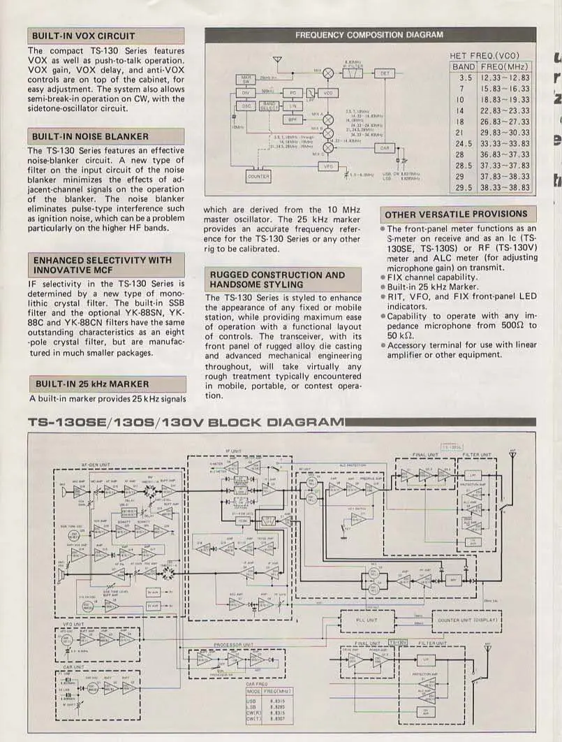
Images and diagrams
- The block diagram illustrates the signal path from the antenna through the IF unit and filter unit to the final amplifier.
- The frequency composition diagram shows the relationship between the VFO, PLL, and heterodyne frequencies for each band.
Model compatibility
- TS-130V is designed for QRP operation.
- Optional filters YK-88SN, YK-88C, and YK-88CN are interchangeable for specific selectivity needs.
- Accessory terminal supports linear amplifiers and other external equipment.

Manual page author
Michael Turner
Technical manual editor
Reviews PDF manuals for structure, safety notes, and practical product details so readers can find the right information quickly.