Lighting / Fixtures
Instruction Manual for True Fine 170002C 4-Light Chandelier
Complete installation and wiring guide for the True Fine 170002C 4-Light Chandelier. Includes assembly steps, wiring diagrams for Group A and Group B connections, safety precautions, and technical specifications.
Quick answers from the manual
Quick answer
- The True Fine 170002C is a 4-light chandelier. Installation involves assembling the stems and canopy, mounting the strap to the outlet box, and connecting wires based on the Group A/Group B classification provided in the manual. p. 1
Key actions
- Assemble the fixture by screwing stems to the body and attaching the canopy. p. 1
- Connect wires using the Group A/Group B table to ensure correct polarity. p. 1
Problems and fixes
Loose wire connection
Re-do steps 3 and 4 of the wiring instruction, ensuring the connector is screwed clockwise until firm.
p. 1Maintenance and reset
- Clean with a soft cloth and mild soap. Avoid abrasive materials. p. 1
Technical specifications
| Parameter | Value | Meaning | Pages |
|---|---|---|---|
| Input voltage | 120V | Operating voltage | p. 1 |
| Rated power | 60W MAX | Maximum bulb wattage | p. 1 |
| Lamp socket | E26 | Bulb base type | p. 1 |
Where to find it in the PDF
- Instruction Manual p. 1
Table of contents
Quick guide from the manual
This document provides the necessary steps to assemble and install the True Fine 170002C 4-Light Chandelier. Safety First: Always switch off the electricity supply at the main breaker before starting any installation work. Allow the fixture to cool for 10 minutes before changing light bulbs. Never connect the ground wire to black or white power supply wires.
Overview and parts
The package includes the following components:
- Fixture body
- Canopy and mounting strap
- Screws and wire nuts
- Stems
- Lamp instruction
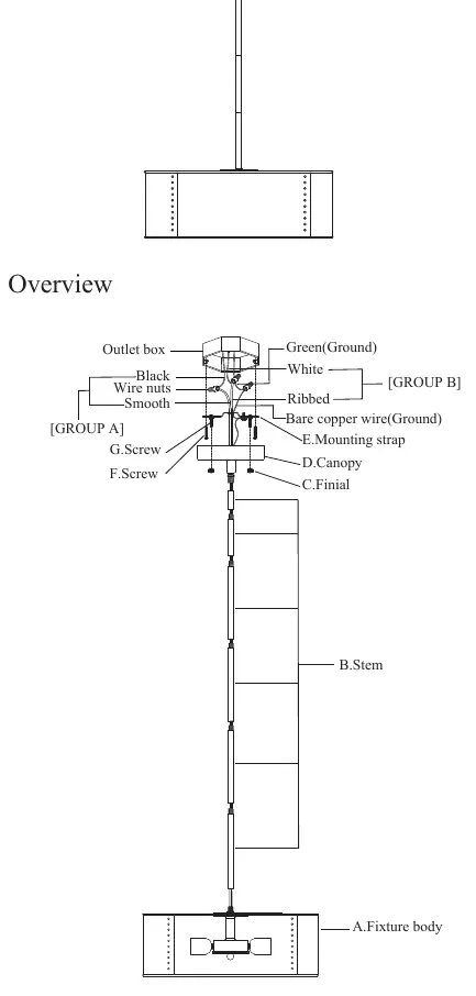
Assembly instructions
- Screw the stems (B) to the fixture body (A) one by one.
- Screw the canopy (D) to the stem (B).
- Fix the mounting strap (E) to the outlet box using screw (F).
- Connect the wires according to the wiring instructions.
- Pass the canopy (D) through the screw (G) and fix it with the finial (C).
Wiring instructions
Proper wiring is critical for safety. Identify your fixture wires and connect them according to the following groups:
- Group A (Connect to Black House Wire): Includes black wires, parallel wires (round & smooth), white/grey wires with tracer, and brown/gold/black wires without tracer.
- Group B (Connect to White House Wire): Includes white wires, parallel wires (square & ridged), white/grey wires without tracer, and brown/gold/black wires with tracer.
Steps:
- Insert the green grounding screw into the mounting bar. Wrap the fixture ground wire around it and connect to the outlet box ground wire using a wire connector.
- Place fixture wires from Group A against the black house wire. Do not twist wires together before using wire connectors.
- Fit a wire connector over the wires and screw clockwise until firm.
- Connect Group B wires to the white house wire in the same manner.
- Gently pull the connector to ensure a firm connection. Ensure no bare wires are visible outside the connectors.
Specifications and maintenance
Technical Specifications:
- Input voltage: 120V
- Rated power: 60W MAX
- Lamp socket: E26
Cleaning: Wipe the fixture with a soft cloth. Clean glass components with mild soap. Do not use abrasive materials, scouring pads, steel wool, or abrasive paper.
Practical help
Common problems
Loose wire connection
Ensure wire connectors are screwed on clockwise until firm. Gently pull the connector to verify it does not come off.
Wiring confusion (Group A vs Group B)
Identify wire type (e.g., smooth vs ridged, tracer vs no tracer) and match to the specific group table provided in the manual.
Grounding issues
Never connect the ground wire to black or white power supply wires. Use the green grounding screw on the mounting bar.
Before use
- Switch off the electricity supply at the main breaker.
- Verify all parts are present (Fixture body, Canopy, Mounting strap, Screws, Stems).
- Identify wire types to determine Group A or Group B connection.
- Ensure you have wire connectors (not supplied).
- Allow 10 minutes for the fixture to cool before handling bulbs.
Images and diagrams
- The overview diagram illustrates the assembly order from the fixture body up to the canopy and mounting strap.
- The wiring table clarifies which wire characteristics (smooth, ridged, tracer) belong to Group A (Black) or Group B (White).
Model compatibility
- Designed for 120V electrical systems.
- Uses E26 base bulbs.

Manual page author
Michael Turner
Technical manual editor
Reviews PDF manuals for structure, safety notes, and practical product details so readers can find the right information quickly.