General / Accessories
Uniview 0231C20R Card Reader User Guide
Quick guide for the Uniview 0231C20R card reader, covering installation steps, wiring, DIP switch settings, and status indicators.
Table of contents
Manual images
Jump to the sectionQuick guide from the manual
This document provides essential installation and configuration instructions for the Uniview card reader. It is intended for use by trained professionals. Key procedures include physical mounting, tail cable wiring, and configuring communication modes (Wiegand or RS485) via DIP switches.
Device Installation
The device requires a 86x86mm or 115x73mm junction box (not included). Ensure the installation surface is flat and stable.
- Determine the position of the junction box and ensure it is securely embedded.
- Secure the mounting bracket to the junction box using the provided M4x35 screws.
- Connect the tail cable according to your network requirements. Secure the tail cable cover plate to the back of the reader using M2.5 screws.
- Align the reader with the bracket protrusions, insert it, and secure it using the M3 security screw at the bottom.
Tail Cable Wiring
The device uses a color-coded tail cable for connectivity:
- Black: GND (Grounding)
- Red: VDD12V (Power)
- Orange/Yellow: RS485_A / RS485_B
- White: TAMPER (Tamper alarm)
- Blue: WEIGAND_BUZZER (Buzzer control)
- Purple/Pink: WIEGAND_ERR / WIEGAND_OK (LED control)
- Green/Brown: WIEGAND_OUT_D1 / WIEGAND_OUT_D0 (Wiegand output)
DIP Switch Settings
DIP switches on the back allow for mode and parameter configuration:

- 1-4: RS485 address bits (requires switch 5 to be ON).
- 5: Card reader mode (ON: RS485, OFF: Wiegand).
- 6: Wiegand protocol (ON: Wiegand 26, OFF: Wiegand 34).
- 7: RS485 termination resistor (ON: Connect, OFF: Disconnect).
- 8: Card security function (ON: Encrypted, OFF: Physical ID only).
Status Description
- Blinking blue, green, red: Startup successful.
- Steady blue: Normal operation.
- Steady green (1s): Authentication successful.
- Steady red (1s): Authentication failed.
- Constant beeps: Tamper alarm triggered.
Manufacturer information
Uniview
Practical help
Common problems
Tamper alarm triggered
The device is emitting constant beeps; check if the device is properly secured to the bracket.
Authentication failed
The device emits three beeps and a steady red light; ensure the card is valid and properly presented.
Communication issues in RS485 mode
For long-distance (>500m) or high-speed (>1Mbps) connections, set DIP switch 7 to ON to enable the termination resistor.
Before use
- Ensure a 86x86mm or 115x73mm junction box is installed.
- Prepare a Phillips screwdriver for installation.
- Verify the power supply provides stable voltage and meets device requirements.
- Plan cable routing before starting installation.
- Ensure the device is protected from liquids and extreme environments.
Specs in practice
- Wiegand Protocol
- Standard interface for connecting card readers to access control panels.
- Card Security Function
- When ON, enables encrypted authentication for CPU cards; when OFF, reads only physical ID.
Images and diagrams
- The back of the device contains the bracket mounting groove, tail cable interface, PSAM card slot, and DIP switches.
- The tail cable cover plate must be secured with the rubber pad facing inward to ensure proper fit.
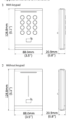
Model compatibility
- Installation methods are identical for models with or without a keypad.
- The device supports both Wiegand and RS485 communication modes.
- Encrypted authentication (DIP switch 8 ON) does not support NFC emulated cards.

Manual page author
David Miller
Documentation analyst
Organizes user manual content into clear summaries, with attention to model details, product context, and everyday usability.