Documents / Warranty Safety
Uniview 0235C80V Villa Door Station User Guide
Quick guide for the Uniview 0235C80V Villa Door Station, covering installation, wiring, nameplate setup, and default network settings.
Table of contents
Manual images
Jump to the sectionQuick guide from the manual
This document provides essential installation and setup instructions for the Uniview Villa Door Station (2-button and 4-button models). It covers physical mounting, cable connections, and initial network configuration. Please note that installation should be performed by a trained professional.
Device Overview
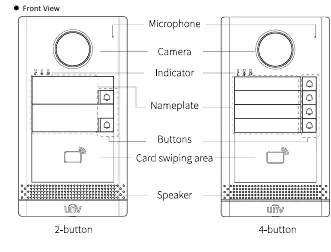
The door station features a camera, microphone, speaker, indicator lights, and call buttons. The rear panel contains the network interface and cable terminal interface. A Micro SD card slot is located on the side for video storage.
Device Installation
Before starting, ensure you have the necessary tools, such as a Phillips screwdriver. The installation process is identical for both 2-button and 4-button models.
Wall Mount
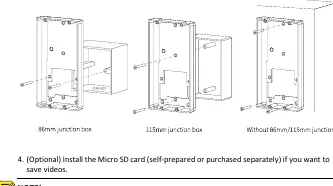
- Use an 86x86mm or 115x73mm junction box if available.
- If using a junction box, align the drill template with the box holes.
- Without a junction box, drill three 30mm-depth holes using a 6mm to 6.5mm drill bit and insert expansion bolts.
- Secure the mounting bracket to the wall or junction box using the provided screws.
- Connect network and power cables to the terminal interface.
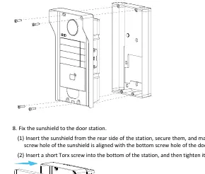
- Fix the door station to the bracket using four long Torx screws.
- Optionally, install a sunshield by securing it from the rear and tightening the bottom screw.
Recess Mount
- Drill a recess in the wall according to the bracket dimensions.
- Secure the recess bracket using four pointed tail cross screws.
- Remove the five limiting parts after securing the bracket.
- Complete the remaining steps (cabling, mounting the station) as described in the Wall Mount section.
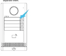
Nameplate Setup
To customize the nameplate: remove the cover and base, write the household or location information on the paper nameplate, place it between the cover and base, and reattach it to the device.
Startup and Default Settings
Connect the device via PoE (network cable) or a power adapter. The default network settings are:
- IP Address: 192.168.1.13
- Username: admin
- Password: 123456
Security Note: It is strongly recommended to change the default password immediately to a strong password containing at least nine characters, including uppercase/lowercase letters, digits, and special characters.
Manufacturer information
Uniview
Practical help
Common problems
Tamper-proof button sounding continuously
Ensure the rubber stopper is correctly mounted to the protrusion position on the bracket to prevent loosening.
Micro SD card not working or damaged
Do not hot-plug the SD card. Always power off the device or follow proper procedures before inserting or removing the card.
Before use
- Plan wiring based on actual networking conditions.
- Prepare a Phillips screwdriver.
- Ensure the power supply provides stable voltage.
- Verify the installation surface is flat and secure.
- Change the default admin password to a strong one.
Specs in practice
- Steady red indicator
- The device is currently calling.
- Steady white indicator
- The device is in an active call.
- Steady green indicator
- The door is open.
Images and diagrams
- The drill template shows alignment holes for both 86mm and 115mm junction boxes.
- The rear view identifies the cable terminal interface and network interface locations.
- The recess mount diagram indicates the required 170mm x 90mm space for the bracket.
Model compatibility
- Supports both 2-button and 4-button configurations.
- Compatible with 86x86mm or 115x73mm junction boxes.
- Requires PoE power source or compatible power adapter.

Manual page author
Michael Turner
Technical manual editor
Reviews PDF manuals for structure, safety notes, and practical product details so readers can find the right information quickly.