Power / Batteries & Chargers
User Manual for V-TAC VT-OH-5K Rechargeable Li-On Battery Module
Quick guide for the V-TAC VT-OH-5K 100AH Rechargeable Li-On Battery Module. Includes installation steps, electrical connection diagrams, safety instructions, and troubleshooting.
Table of contents
Manual images
Click an image to enlargeQuick Guide
This document provides essential instructions for the V-TAC VT-OH-5K battery module. Always ensure the system is installed by trained personnel. Before starting, verify that your inverter is compatible and that all safety gear (isolation gloves, safety goggles, safety shoes) is used during installation. Ensure the installation site is flat, level, and free from flammable materials.
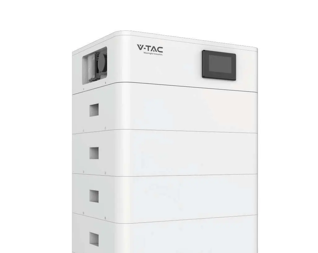
Product Overview
The V-TAC 51.2V 100AH lithium iron phosphate (LiFePO4) battery system is designed for energy storage. It features an integrated Battery Management System (BMS) for protection against over-discharge, over-charge, over-current, and abnormal temperatures. The system supports parallel configuration for capacity expansion.
Installation
The installation process involves mechanical assembly followed by electrical connection. Ensure the environment is indoor, away from direct sunlight, wind, and corrosive gases. The optimal ambient temperature is 15°C to 30°C.
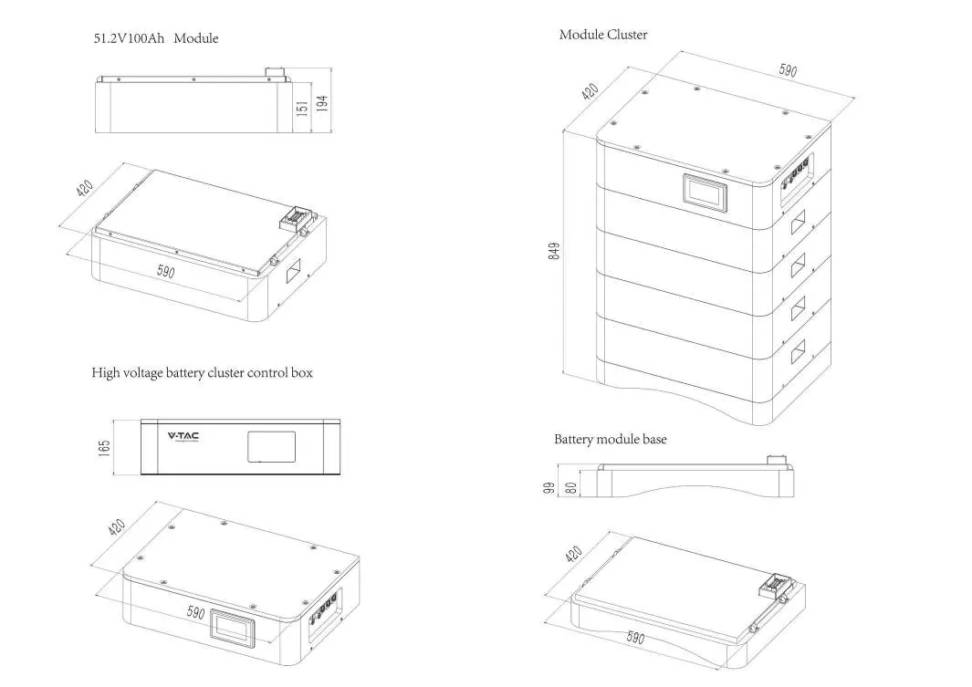
Mechanical Installation Steps:
- Install the Battery module base.
- Install the Battery module.
- Install the High voltage battery cluster control box.
- Install side fastening screws.
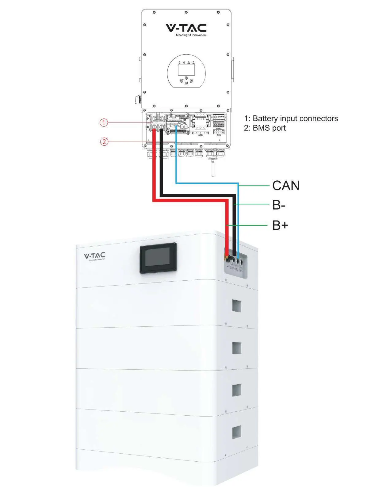
Electrical Connection
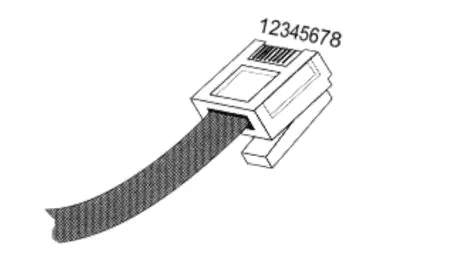
Connect the battery system to the inverter using the provided cables. Ensure the voltage and polarity are correct before turning on the inverter. The system uses CAN communication for interaction with the inverter.
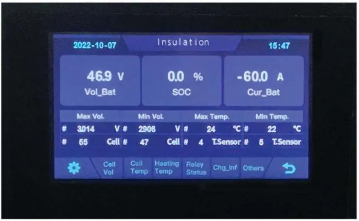
Operation and Display
To start the system, open the BMS ON/OFF switch and wait for the screen to display normal status. Once confirmed, open the air switch. The LCD screen displays real-time voltage, current, SOC (State of Charge), and temperature. If the screen shows ALM (Alarm) status, refer to the troubleshooting section.
Troubleshooting
If the system encounters issues, check the following:
- Indicator does not respond: Check if the total voltage is lower than 40V*N.
- No DC output: The system may be in over-discharged protection mode; check battery data on the monitor.
- Short power supply time: Battery capacity may have decreased; consider adding more modules.
- Cannot charge to 100%: Charging voltage may be too low; adjust to 57V*N.
- Sparks on power-on: Indicates a short circuit; turn off the battery immediately and inspect wiring.
Practical help
Common problems
Indicator does not respond after power on
Check the total voltage; it must be higher than 40V*N.
No DC output
Read battery information on the monitor; the system may be in over-discharged protection.
DC power supply time is too short
Battery capacity may have decreased; consider replacing the battery or adding more modules.
Battery cannot be fully charged to 100%
Charging voltage is too low; adjust the charging voltage to 57V*N.
Power cable sparks when powered on
Indicates a power connection short-circuit; turn off the battery and check for the cause of the short circuit.
Before use
- Verify that the PV power generation equipment or power supply has a DC output interface.
- Measure DC output voltage to ensure it meets requirements.
- Ensure the maximum discharge current of the power source is higher than the battery's maximum charging current.
- Ensure the installation site is flat, level, and away from the sea/brine.
- Wear isolation gloves, safety goggles, and safety shoes.
- Ensure no flammable or explosive materials are near the installation site.
Specs in practice
- Nominal Voltage
- 51.2V per module.
- Nominal Capacity
- 100Ah.
- Working Temperature
- 0°C to 45°C for charging; -10°C to 55°C for discharging.
Images and diagrams
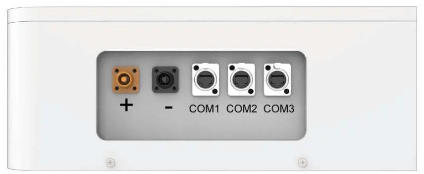
- The front interface includes the power connector, screen, air switch, and communication ports.
- The electrical connection diagram illustrates the B+, B-, and CAN connections between the battery and the inverter.
Model compatibility
- Compatible with inverters supporting CAN communication.
- Do not mix batteries from different manufacturers, types, or models.
- Do not mix old and new batteries.

Manual page author
Emily Carter
User documentation editor
Prepares concise manual descriptions and highlights the most useful setup, operation, and maintenance information for readers.