HVAC / Air Conditioners
User Manual for Velit 2000R Mini Rooftop Air Conditioner
Quick guide for the Velit 2000R Mini Rooftop Air Conditioner. Includes installation steps, operating modes, control panel functions, and troubleshooting error codes.
Quick answers from the manual
Quick answer
- The Velit 2000R Mini is a rooftop DC air conditioner. Installation requires a 14-1/4 x 14-1/4 roof opening, 6AWG wiring, and proper sealing. Operation is controlled via the display panel or remote, with modes including Sleep, ECO, Cooling, and Turbo. p. 1, 5, 6, 9
Key actions
- Install the unit p. 5, 6, 7
- Operate the unit p. 8
First start
- Ensure the unit is installed by qualified personnel, connected to a proper DC power source (12V or 48V), and the sealing gasket is applied correctly. p. 3, 5, 6
Show 4 more answers Show less
Problems and fixes
E0
Ambient temperature sensor issue. Check white 2-pin connector.
p. 11
E4/EL
Low voltage. Check battery and wiring.
p. 11Error codes
| Code | Meaning | Action | Pages |
|---|---|---|---|
| E0 | Ambient temperature sensor | Check white 2-pin connector | p. 11 |
| E4/EL | Low-voltage | Check system and battery voltage | p. 11 |
Technical specifications
| Parameter | Value | Meaning | Pages |
|---|---|---|---|
| Cooling Capacity | 7500BTU / 8000BTU | Cooling power based on voltage | p. 4 |
Where to find it in the PDF
- Specifications p. 4
- Installation p. 5, 6, 7
- Operation p. 8, 9
- Troubleshooting p. 11
Table of contents
Manual images
Click an image to enlargeQuick guide from the manual
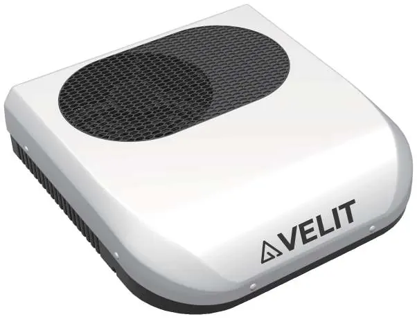
The Velit 2000R Mini is a rooftop DC air conditioner designed for vehicle installation. This manual provides essential safety, installation, and operation instructions. Always ensure the unit is installed by qualified personnel and that all electrical connections are secure.
Safety Information
- Installation: Must be performed by qualified personnel familiar with the risks.
- Modifications: Do not modify the unit in any way.
- Environment: Do not use in or near flammable environments. Do not use when ambient temperature is below 40°F (risk of frost).
- Cleaning: Do not power wash or use detergents to clean the unit.
- Supervision: Keep out of reach of children.
Specifications
The unit is available in DC12V and DC48V configurations.
- Cooling Capacity: 7500BTU (12V) / 8000BTU (48V)
- Operating Current: 15-50A (12V) / 5-14A (48V)
- Rated Power: 600W (12V) / 670W (48V)
- Noise Level: 55dB (ECO) / 65dB (Boost)
- Weight: 61.7lbs / 28KG
Installation
Preparation: Ensure the roof opening is 14-1/4 x 14-1/4 inches. If the location is different, ensure at least 10 inches of clearance from the roof edge and a slope of less than 15 degrees.
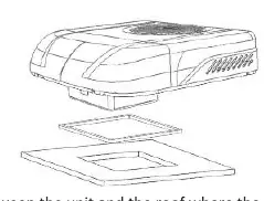

- Wiring: Route 6AWG power cable to the roof opening, leaving at least 6 inches of slack.
- Sealing: Clean the surface between the unit and the roof. Apply sealant to the bottom of the sealing gasket and place it on the roof opening.
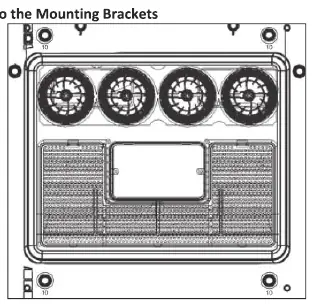
- Mounting: Place the unit over the opening, pull the power cable through, and secure using the provided M8 threaded rods and mounting brackets. Hand-tighten nuts to 4.5-5.6NM. Do not overtighten.
- Wiring Connection: Connect the power cable to the battery. Ensure fuse boxes are present on both positive and ground lines.
- Decor Panel: Secure the interior decor panel using the provided self-tapping screws.
Operation
The unit can be controlled via the display panel or the remote control.
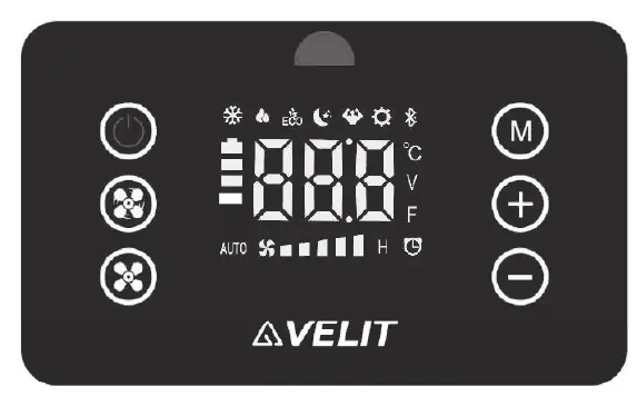
- Modes: Sleep, ECO, Cooling, and Turbo.
- Control Panel: Use the Power button to turn the unit on/off. Use the Mode button to cycle through settings. Fan speed and temperature can be adjusted using the +/- buttons.
- Temperature Units: Switch between °C/°F by long-pressing the Mode button for 3 seconds while the unit is on.
Troubleshooting
If an error occurs, the error icon will flash with a code. Common issues include:
- E0/E1: Sensor issues. Check the white/red 2-pin connectors on the display panel.
- E4/EL: Low voltage. Check battery and wiring connections.
- EU: Controller overheated. Let the unit sit for 10 minutes and restart.
Practical help
Common problems
Unit does not turn on or displays E4/EL (Low-voltage)
Check battery voltage and ensure wiring is connected properly with no loose connections. The unit triggers this error if voltage drops below 10.5V.
E0 or E1 error codes
These indicate sensor issues. Use a flathead screwdriver to pry open the display panel and ensure the white (E0) or red (E1) 2-pin connector is seated properly.
EU error code
Controller overheated. Allow the unit to sit for ten minutes before restarting.
Before use
- Verify the roof opening is 14-1/4 x 14-1/4 inches.
- Ensure the installation location has at least 10 inches of clearance from the roof edge.
- Use 6AWG power cable for installation.
- Disconnect all power supplies (battery, generator, shore power) before starting installation.
- Apply sealant to the sealing gasket before placement.
Show more Show less
Specs in practice
- Cooling Capacity
- 7500BTU for 12V models and 8000BTU for 48V models.
- Operating Current
- 15-50A for 12V models and 5-14A for 48V models.
Images and diagrams
- The manual provides diagrams for roof opening dimensions, sealing gasket application, mounting bracket installation, and decor panel attachment.
Model compatibility
- Designed for rooftop installation on vehicles.
- Requires 6AWG power cable.
- Compatible with DC12V or DC48V systems.

Manual page author
David Miller
Documentation analyst