Power / Solar Systems
Ventev 14x12x6 NEMA 4X Enclosure with Integrated Directional Antenna Installation Guide
Quick installation guide for the Ventev 14x12x6 NEMA 4X Enclosure with Integrated Directional Antenna. Learn how to mount the enclosure, install the cable gland, and connect the Cisco 9130E access point and DART cables.
Table of contents
Manual images
Click an image to enlargeQuick Installation Guide
This document provides instructions for installing the Ventev 14x12x6 NEMA 4X Enclosure with an integrated directional antenna. Follow these steps to ensure proper setup and connectivity.
Mounting the Enclosure
Begin the installation by attaching the mounting feet to the enclosure. Once the feet are attached, hang the enclosure in the desired location.
Access Point Installation
This enclosure is specifically designed to accommodate the Cisco 9130E access point. To install the mounting bracket:
- Orient the Cisco low-profile bracket as required.
- Attach the mounting bracket to the back plate using four #8 screws.
- Note: You must remove the two right-side screws from the antenna swing-out panel to gain access to the back plate.
Cable Connections
Follow these steps to complete the wiring:
- Install the included cable gland on the box and route the Ethernet cable inside.
- Plug the Ethernet cable into the access point and slide the access point into the mounting bracket.
- Connect the DART cable attached to the antenna on the separate swing-out panel.
- Replace the two screws to secure the antenna swing-out panel.
Support
For further assistance, please visit www.ventev.com/infra, email [email protected], or call 800.851.4965.
Official resources from the manual
Practical help
Common problems
Cannot access the back plate to attach the mounting bracket
Remove the two right-side screws from the antenna swing-out panel to allow access to the back plate.
Before use
- Attach mounting feet to the enclosure
- Ensure Cisco 9130E access point is available
- Have four #8 screws ready for bracket mounting
- Verify the desired mounting location
Images and diagrams
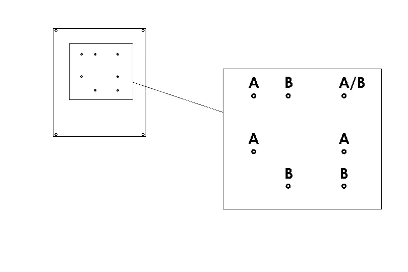
- Figure 1 illustrates the mounting bracket orientation and the screw configuration for the back plate.
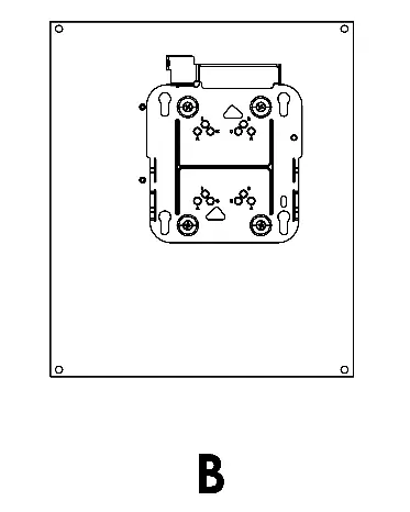
- Figure 2 shows the enclosure with the antenna swing-out panel and the location for the DART cable connection.
Model compatibility
- Designed for use with the Cisco 9130E access point.

Manual page author
Michael Turner
Technical manual editor
Reviews PDF manuals for structure, safety notes, and practical product details so readers can find the right information quickly.