Power / Solar Systems
Installation and Operation Manual for Ventev 052124D Solar Power System
Quick guide for the Ventev 052124D Solar Power System. Includes installation steps, wiring diagrams, commissioning checklist, maintenance tips, and troubleshooting procedures.
Table of contents
Manual images
Click an image to enlargeQuick Guide
This document provides instructions for the installation, operation, and maintenance of the Ventev Solar Power System. Key steps include site selection, mechanical assembly of the solar array, electrical wiring, and system commissioning. Always ensure the solar module is free of shade and faces the equator for maximum efficiency. Before performing any electrical work, ensure all breakers are in the OFF position.
System Overview
The system consists of solar modules, batteries, and a solar charge controller. The controller regulates the charging current to the battery bank and includes a Low Voltage Disconnect (LVD) feature to prevent battery over-discharge. The system is designed to operate in both 12V and 24V configurations (multiply voltage values by 2 for 24V systems).
Installation
Tools Required
- Phillips Head and Straight Blade Screwdrivers
- Wire Strippers and Wire Cutters
- Multimeter
- Socket Set
- Cable Ties
- Compass (for orientation)
Site Location
Mount the solar modules in an area free of shade, as shading significantly reduces power output. Orient the modules facing the equator. Use a GPS or magnetic compass to determine true north and south.
Mechanical Assembly
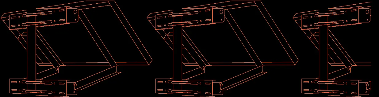
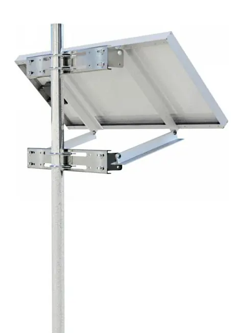
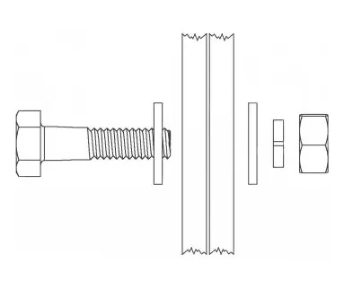
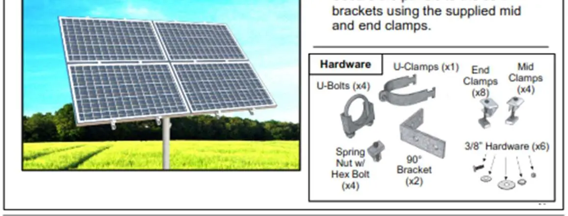
The system supports side-of-pole and top-of-pole configurations. Ensure the mounting pole (pipe stand) is properly secured. Use the provided hardware sets to bolt the solar modules to the brackets. Adjust the channel position to achieve the desired tilt angle.
System Wiring
Before wiring, turn all breakers to the OFF position. Ground the electrical panel to the site ground using a bare ground wire. Connect the battery cables (red to positive, black to negative) and terminate the solar array and load wires to the designated terminals on the din rail.
System Checkout and Commissioning
After installation, perform the following checks:
- Verify all hardware and fasteners are tight.
- Ensure wires are properly installed and secured with no exposed copper.
- Confirm the solar module faces the equator with the correct tilt.
- Use a multimeter to verify the module's open circuit voltage and current.
- Verify battery voltage is at least 12.4VDC.
- Turn on the battery breaker and verify the green Battery Status light.
- Turn on the solar and load breakers and verify the green Charging Status light.
Recommended Maintenance
- Solar Panel Cleaning: Clean the glass with a soft cloth, water, and biodegradable soap as needed to remove dirt and dust.
- Avoid Shading: Regularly trim trees or remove obstructions that may cast shadows on the panels.
- Regular Inspection: Inspect all electrical connections for looseness or corrosion. Check the module back surface for damage and seal any punctures with RTV sealant.
Troubleshooting
If the system fails to operate within design parameters, check the following:
- Temperature: Extreme heat can cause overcharging, while cold can reduce capacity.
- Shading/Angle: Ensure the panel is not obstructed and is at the correct angle.
- Battery Configuration: Verify the battery bank has the correct series-parallel configuration.
- Connections: Check for loose or corroded terminals, fuses, or crimp connectors.
- Load: Ensure the connected load does not exceed the system design specifications.
If issues persist, contact technical support at 1-800-759-9996 or email [email protected].
Practical help
Common problems
System batteries are under-charged
Check for shading on the solar panels, verify the battery bank configuration, or check for concealed loads drawing power.
Severe voltage drop (power loss)
Inspect wiring for loose or damaged connections; ensure wires are of appropriate length and gauge.
Battery not charging
Check charge controller status LEDs; verify solar array output (should be 36-44V for a 24V system in sunny conditions).
Before use
- Ensure the installation site is free of shade.
- Verify all mechanical hardware and fasteners are tight.
- Confirm the solar module is oriented toward the equator.
- Ensure all breakers are in the OFF position before wiring.
- Verify battery voltage is at least 12.4VDC (or 24.8VDC for 24V systems).
Specs in practice
- LVD (Low Voltage Disconnect)
- Disconnects the load if battery voltage falls to 11.5VDC (or 23VDC for 24V systems) to prevent permanent battery damage.
- Open Circuit Voltage (VOC)
- The voltage of the solar module when not connected to a load; used to verify panel health.
- Short Circuit Current (ISC)
- The current of the solar module when terminals are shorted; used to verify panel health.
Images and diagrams
- Side-of-Pole Mount: Shows the arrangement of solar brackets, wind braces, and U-bolts for pole mounting.
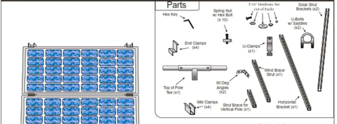
- Top-of-Pole Mount: Illustrates the assembly of solar rails, horizontal brackets, and clamps for 3 or 4 panel configurations.
Model compatibility
- Designed for 12V and 24V systems (multiply voltage values by 2 for 24V).
- Compatible with standard pole-mount structures.

Manual page author
Emily Carter
User documentation editor
Prepares concise manual descriptions and highlights the most useful setup, operation, and maintenance information for readers.