Furniture / Home Furnishing
Installation Guide for VEVOR 12x10x6 Inch Electric Metal Box
A comprehensive installation guide for the VEVOR 12x10x6 inch electric metal box, covering mounting plate, sealing plate, wall pendants, grounding wire, door, and lock assembly.
Table of contents
Manual images
Jump to the sectionQuick guide from the manual
This document provides installation instructions for the VEVOR 12x10x6 inch electric metal box. Most components, including the mounting plate, grounding wire, door, and lock, are pre-assembled at the factory. The guide details how to install the bottom sealing plate and wall mounting pendants, as well as how to adjust or replace the door and lock components if necessary.
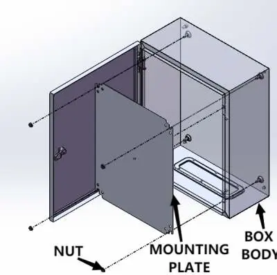
Mounting plate installation
The mounting plate is secured to the box body using 4 M8 hex head flange nuts. This component is pre-assembled at the factory.
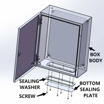
Bottom sealing plate installation
The bottom sealing plate can be installed based on your specific usage requirements. Use the provided M5x10mm cross self-tapping screws to assemble the sealing washer and the bottom sealing plate to the box body.
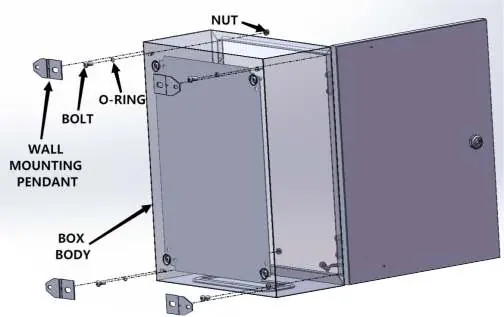
Wall mounting pendants installation
To mount the box on a wall, use 4 wall mounting pendants. Secure each pendant using an M8x16mm hex head bolt, an M8 O-ring, and an M8 nut.
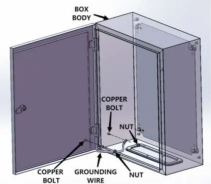
Grounding wire installation
The grounding wire is connected to the box door and the box body using 2 M6 hex head flange nuts on M6x12mm copper bolts. This is pre-assembled at the factory.
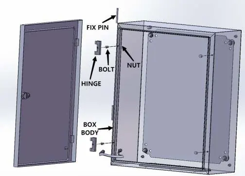
Box door installation
The door is attached to the box body using a hinge assembly consisting of an M6x12mm flat head cross screw, an M6 O-ring, and an M6 hex head flange nut. The door is secured to the hinge with a fixed pin. This is pre-assembled at the factory.
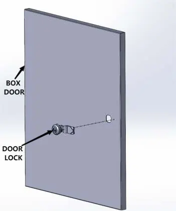
Door lock installation
The door lock is secured to the box door using lock nuts. Use the provided matched key to open and close the door. Warning: When locking the door, turn the lock core 90 degrees from the vertical to the horizontal position to ensure the best protection level.
Manufacturer information
VEVOR
Practical help
Common problems
Door not locking securely
Ensure the lock core is turned 90 degrees from the vertical to the horizontal position.
Before use
- Verify all pre-assembled components (mounting plate, grounding wire, door, lock) are secure.
- Determine if the bottom sealing plate is required for your installation environment.
- Ensure you have the matched key for the door lock.
- Check that the lock core is in the correct horizontal position for maximum protection.
Specs in practice
- M8x16mm hex head bolt
- Hardware used for securing wall mounting pendants.
- M5x10mm cross self-tapping screw
- Hardware used for attaching the bottom sealing plate.
- Lock core 90 degree turn
- Required action to engage the locking mechanism properly.
Images and diagrams
- The diagrams illustrate the specific hardware (bolts, nuts, O-rings) required for each assembly step.
- Arrows indicate the exact placement of components like the grounding wire and hinge pins.
Model compatibility
- The bottom sealing plate is optional and should be installed based on specific usage requirements.

Manual page author
Michael Turner
Technical manual editor
Reviews PDF manuals for structure, safety notes, and practical product details so readers can find the right information quickly.