Power / Batteries Chargers
User Manual for 2E 11KW Twin Solar Inverter / Charger
Quick guide for the 2E 11KW Twin Solar Inverter / Charger, covering installation, wiring, LCD settings, operation modes, and troubleshooting.
Table of contents
Manual images
Jump to the sectionQuick guide from the manual
This document provides essential instructions for the 2E 11KW Twin Solar Inverter / Charger. It covers system installation, electrical wiring, configuration, and troubleshooting. Always ensure all electrical work is performed by qualified personnel.
Device Overview
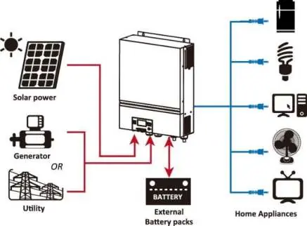
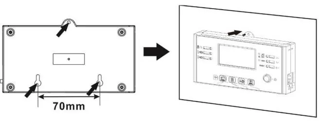
The 11KW Twin is a multifunctional inverter combining inverter, solar charger, and battery charger functions. It features a detachable LCD control module, built-in Wi-Fi for mobile monitoring, and supports parallel operation.
Installation
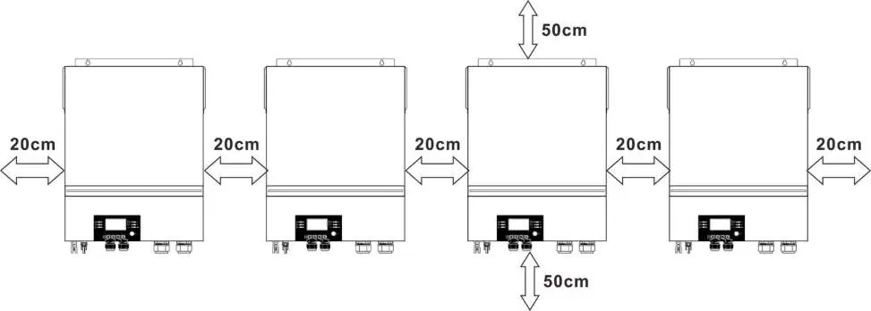
Ensure the unit is mounted on a non-flammable surface (concrete or similar). Maintain at least 20cm of clearance on the sides and 50cm above and below for proper heat dissipation. The operating temperature range is 0°C to 55°C.

Wiring
- Battery Connection: Use recommended 1*3/0AWG cables. Ensure correct polarity and tighten terminals to 5 Nm.
- AC Input/Output: Connect AC input and output according to the markings. Ensure the PE (ground) wire is connected first.
- PV Connection: Use only monocrystalline, polycrystalline (Class A), or CIGS modules. Ensure the PV array voltage does not exceed 500V DC.
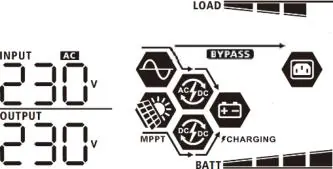
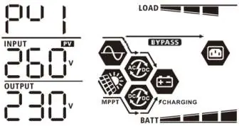
Operation
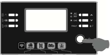
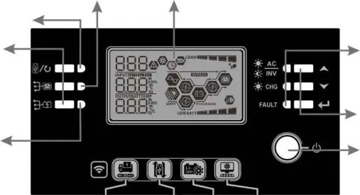
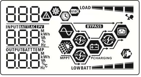
Use the power switch on the display panel to turn the unit on. The LCD provides real-time status, including input/output voltage, battery capacity, and load percentage. Use the function keys to navigate menus and configure settings.
LCD Settings
To enter settings, hold the Enter button for 3 seconds. Use the Up/Down keys to select programs. Key settings include:
- 01: Output source priority (Utility, Solar, or SBU).
- 02: Maximum charging current.
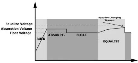
- 05: Battery type selection.
- 28: Parallel/3-phase operation mode.
Troubleshooting
The unit displays fault codes on the LCD. Common issues include:
- F01: Fan blocked.
- F02: Over-temperature.
- F03/F04: Battery voltage too high/low.
- F05: Output short circuit.
For persistent issues, contact the authorized service center: IP LOGIC, Kyiv, Ukraine. Phone: 0 800 300 345; (044) 230 34 84; (044) 390 55 12. Website: https://service.erc.ua
Official resources from the manual
Manufacturer information
2E
Practical help
Common problems
Unit turns off during startup
Battery voltage is too low (<1.91V/cell). Recharge or replace the battery.
No display after power on
Check battery connection and polarity. Recharge or replace the battery.
Utility is present but unit runs on battery
Check AC input breaker and cable connection. Verify input voltage range settings.
Fault code 07 (Overload)
Reduce the connected load by turning off some appliances.
Before use
- Ensure the mounting surface is non-flammable.
- Verify that all wiring (battery, AC, PV) is performed by a qualified professional.
- Check that battery cables are of the recommended size and length.
- Ensure the PV array voltage is within the 90V-450V MPPT range and below 500V.
- Confirm that the battery type is correctly set in Program 05.
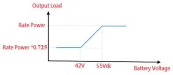
Specs in practice
- Max PV Array Power
- 11000W total capacity.
- MPPT Voltage Range
- 90V to 450V DC for optimal solar charging.
- Max Charging Current
- 150A total (AC + Solar).
Images and diagrams
- Figure 1: Overview of the hybrid PV system showing connections between solar panels, utility/generator, battery, and home appliances.
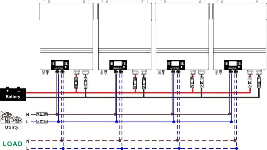
- Parallel connection diagrams show how to link multiple units for single-phase or 3-phase systems.
Model compatibility
- Compatible with lead-acid (flooded, AGM, gel) and lithium batteries.
- Requires specific communication cables for lithium battery BMS integration.
- Supports parallel operation of up to 6 units.

Manual page author
Emily Carter
User documentation editor
Prepares concise manual descriptions and highlights the most useful setup, operation, and maintenance information for readers.