Power / Solar Inverters
Installation Guide for Acuity Brands Factor Series Horticulture LED Lighting System
Comprehensive installation and setup guide for the Acuity Brands Factor Series Horticulture LED Lighting System. Includes mounting instructions, electrical wiring, dimming setup, and safety specifications.
Table of contents
Manual images
Click an image to enlargeQuick Guide from the Manual
The Acuity Brands Factor Series is a professional horticulture LED lighting system. Before installation, ensure the power is off. The system requires specific ambient temperature ranges: 32°F-86°F (0-30°C) for VAFS 2, and 32°F-104°F (0-40°C) for VAFS 4, 5, or 6. Mechanical ventilation is required to maintain these temperatures. A critical step for operation is the installation of the shorting cap on the final lightbar in the array; without it, the system will not light.
Safety Warnings
- Electric Shock: Turn off power before installation, inspection, cleaning, or removal. Follow lock-out/tag-out procedures.
- Fire Hazard: Maintain a minimum 3-inch distance from the lightbar and driver to any combustible material. Maintain a 3-inch clearance between lightbars and drivers.
- Installation: The lightbar must be installed lens down with a minimum 6-inch distance to anything below.
- Cables: Do not conceal or extend cables through walls, floors, or ceilings.
- Photobiological Safety: Possibly hazardous optical radiation. Do not stare at the operating lamp.
Components
The system consists of:
- Factor Series lightbars.
- GEPSC210-600 series LED Driver.
- Optional interconnection cables (VAFEX3FT, VAFEX).
- Mounting accessories (Rolling Rack Mounts, Suspended Wire Form Supports).
Mounting Instructions
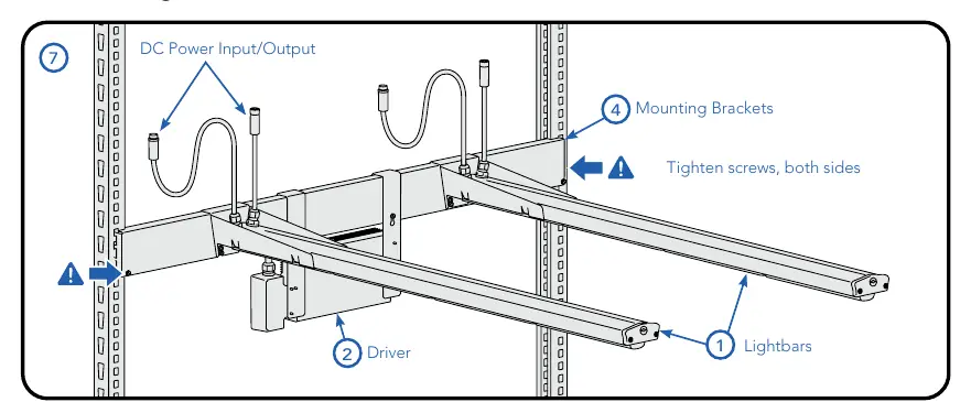
Rolling Rack Mount
- Attach the horizontal bracket to the rack strut.
- Secure the bracket to the strut by tightening the two screws at each end.
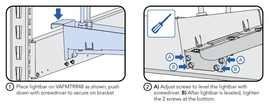
- Place the lightbar on the mount.
- Use a screwdriver to push down and secure the lightbar onto the bracket.
- Adjust leveling screws to level the lightbar, then tighten the bottom screws.
Suspended Mount
- Use two wireform supports (VAFMTSB).
- Attach supports by pushing them up into the slots on the underside of the lightbar.
- Suspend the lightbar from the support structure or cables.
Electrical Connections
Important: Do not make or break electrical connections while power is applied.
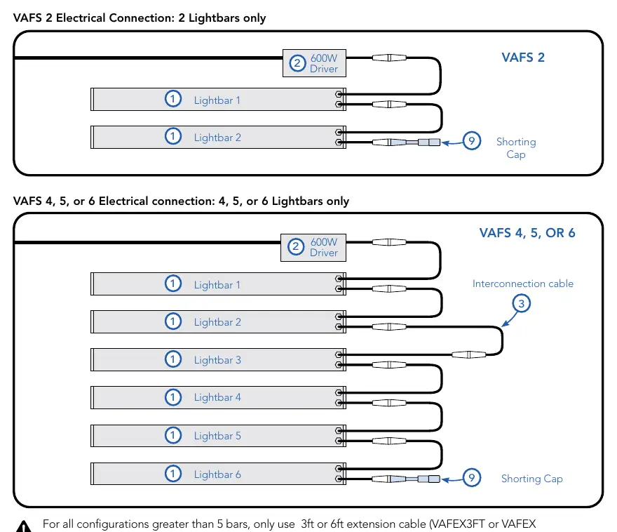
- Connect the driver output to the first lightbar using a 30-inch interconnection cable.
- Daisy-chain subsequent lightbars using the 6-inch cables.
- Shorting Cap: You must connect the shorting cap to the last lightbar's 6-inch cable. The array will not function without this.
- VAFS 2: Only 2 lightbars should be connected.
- VAFS 4, 5, or 6: A minimum of 4 and a maximum of 6 lightbars can be connected.
Wired Dimming Connections
The system supports 0-10V dimming. To connect:
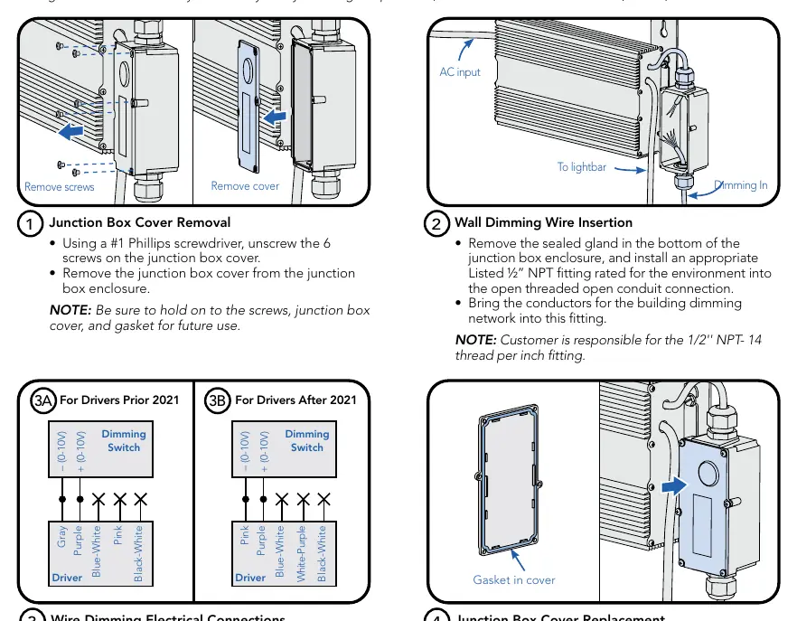
- Remove the junction box cover using a #1 Phillips screwdriver.
- Remove the sealed gland and install a 1/2-inch NPT fitting.
- Bring dimming network conductors into the fitting.
- Connect wiring to Dim+ and Dim- terminals.
- Insulate unused wires (black-white, pink, blue-white, or white-purple depending on driver version).
- Replace the junction box cover, ensuring the gasket is seated correctly.
Maintenance
To maximize longevity, ensure the lightbar and driver are kept clean and free of dust, oil, or debris. Do not apply film to the lens or cover the driver.
Practical help
Common problems
The light array will not turn on.
Ensure the shorting cap is securely connected to the last lightbar in the daisy chain.
Lightbar overheating.
Verify that mechanical ventilation or cooling is active and that ambient temperatures are within the specified limits (32°F-86°F for VAFS 2; 32°F-104°F for VAFS 4, 5, 6).
Dimming is not functioning.
Verify the polarity of the 0-10V Dim+ and Dim- connections and ensure all unused wires are properly insulated.
Before use
- Verify ambient temperature is within the rated range for your specific model.
- Ensure power is disconnected before starting installation.
- Confirm minimum 3-inch clearance from combustible materials.
- Check that the lightbar is installed lens down.
- Verify the shorting cap is available for the final lightbar.
- Ensure all cables are visible and not concealed within building structures.
Specs in practice
- Ambient Temperature
- The operating temperature range for the environment; mechanical cooling is required if exceeded.
- Shorting Cap
- A required terminator for the lightbar array; the system will not operate without it.
- 0-10V Dimming
- Allows for light output adjustment from 0% to 100%.
Images and diagrams
- Rolling Rack Mount: Shows the attachment of brackets to struts and lightbars to brackets.
- Electrical Connection: Illustrates the daisy-chain wiring sequence and the placement of the shorting cap.
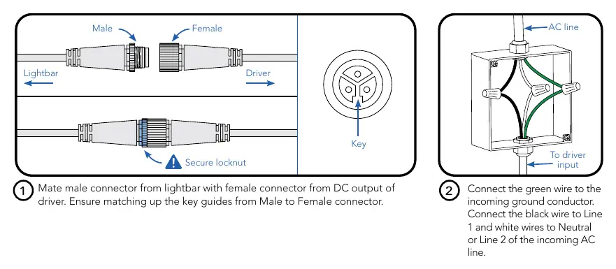
- Dimming Wiring: Details the junction box access and connection points for dimming controls.
Model compatibility
- VAFS 2: Supports exactly 2 lightbars.
- VAFS 4, 5, or 6: Supports a minimum of 4 and a maximum of 6 lightbars.
- Extension cables (VAFEX3FT/VAFEX) are required for configurations greater than 5 bars.

Manual page author
Emily Carter
User documentation editor
Prepares concise manual descriptions and highlights the most useful setup, operation, and maintenance information for readers.