Garden / Grow Lights
User Manual for IOTA IISM Modular Inverter Series
Quick guide for the IOTA IISM Modular Inverter Series (1000W-2000W). Includes startup/shutdown procedures, front panel operation, maintenance schedules, and troubleshooting.
Table of contents
Manual images
Click an image to enlargeImportant Information
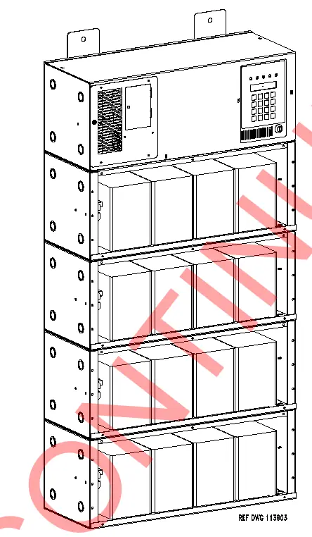
This manual provides instructions for the IOTA IISM Modular Inverter Series (1000W-2000W). This unit is a microprocessor-controlled PWM pure sine wave inverter designed for emergency lighting loads. It features an automatic 3-rate battery charger, self-testing capabilities, and a digital meter display. The unit is intended for indoor use only.
Safety Precautions
- Lethal Voltages: This unit contains lethal voltages. All repairs and service must be performed by authorized service personnel only. There are no user-serviceable parts inside.
- Battery Handling: Use caution when servicing batteries. They contain acid or alkali and can cause burns. If fluid spills on skin or eyes, flush with fresh water and contact a physician immediately.
- Environment: Do not install outdoors, near heaters, or in high-temperature locations. Ensure the area is clean, cool, dry, and well-ventilated.
- Tampering: Mount in locations where unauthorized personnel cannot access the unit.
Startup and Shutdown Procedures
Startup Procedure:
- Verify the installation switch below the front panel is in the OFF position.
- Verify AC input is disconnected.
- Turn on the DC Circuit Breaker CB1.
- Energize the Mains AC input via the upstream distribution panel breaker.
- Turn the installation switch to the ON position. The display should illuminate, and the unit will begin charging.
- Turn on the output circuit breaker(s).
Shutdown Procedure:
- Interrupt AC Mains via the distribution panel or input circuit breaker.
- Turn the installation switch on the inverter chassis to the OFF position.
- Turn off the DC Circuit Breaker CB1.
Front Panel Operation
The front panel includes a 2x20 alphanumeric LCD display, 5 status LEDs, and a 4x4 keypad. Functions are divided into Meter, Control, and Program menus.
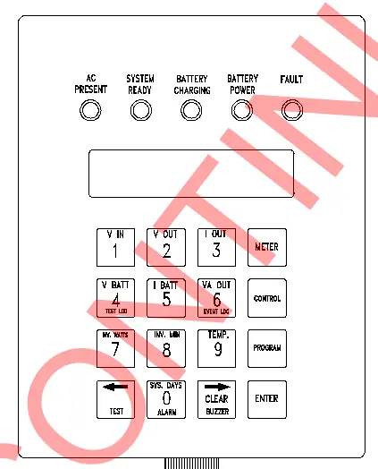
- Meter Functions: Allows monitoring of Voltage Input/Output, Current Output, Battery Voltage/Current, VA Output, Inverter Watts, Inverter Minutes, Temperature, and System Days.
- Control Functions: Provides access to Test Logs, Event Logs, manual testing, Alarm Logs, and Buzzer Silence.
- Program Functions: Password-protected (default 1234). Allows configuration of Date, Time, Test schedules, Load Reduction, and various Alarm thresholds (Low/High VAC, Ambient Temp, Near Low Battery).
Maintenance
Periodic maintenance ensures long-term operation. The system performs self-tests monthly (5 minutes) and annually (90 minutes). Key maintenance tasks include:
- Battery Inspection: Check connections for tightness and corrosion every 6 months.
- Cleaning: Keep air vents free of obstructions. Clean dust from inside the cabinet and fans annually.
- Testing: Perform manual tests only when critical loads are connected.
Troubleshooting
If the system fails to operate, check the following:
- Inverter will not run during power failure: Check if the installation switch is OFF, DC circuit breaker is tripped, or if there is no AC input.
- System overheating/smells: Check for blocked vents or high ambient temperatures.
- Battery voltage low/non-existent: Inspect battery connections, fuses, and battery health.
Practical help
Common problems
Inverter will not run during power failure
Verify the installation switch is ON, the DC circuit breaker is closed, and the AC input is connected.
System overheating or smells
Check for blocked air vents and ensure the ambient temperature is within the operating range (0°C to 40°C).
Battery voltage low or non-existent
Inspect battery connections for tightness and corrosion, and check battery fuses.
Before use
- Ensure the installation switch is in the OFF position.
- Verify AC input is disconnected.
- Complete and return the warranty registration card.
- Ensure the environment is clean, cool, and dry.
- Check that the unit is mounted in a secure location.
Specs in practice
- L.V.D. (Low Voltage Disconnect)
- Protects the battery from permanent damage by shutting down the inverter when battery voltage reaches 85% of nominal.
Images and diagrams
- The front panel features a 2x20 LCD display, 5 status LEDs (AC Present, System Ready, Battery Charging, Battery Power, Fault), and a 4x4 keypad for system interaction.
Model compatibility
- Compatible with lighting loads including quartz, HID, incandescent, fluorescent, and halogen.
- Compatible with generators (10x unit size or larger).

Manual page author
Michael Turner
Technical manual editor
Reviews PDF manuals for structure, safety notes, and practical product details so readers can find the right information quickly.