Industrial / Gas Detection
Installation and Operation Manual for AGS Merlin 1500S Gas and Ventilation Interlock System
Quick guide for the AGS Merlin 1500S gas and ventilation interlock system. Includes installation steps, wiring diagrams, switch settings, operation procedures, and maintenance tips.
Table of contents
Manual images
Click an image to enlargeQuick Guide
The Merlin 1500S is a gas and ventilation interlock system designed for commercial kitchens. It ensures that the gas solenoid valve cannot be opened unless the ventilation system is proven to be working effectively. The system monitors fans via air pressure switches or current monitors and can integrate with various gas sensors (CO2, natural gas, CO, LPG).
Installation
The unit is designed for surface mounting. It must be installed by a licensed, insured contractor.
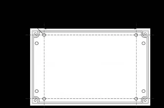

- Mounting: Place the panel 48-60 inches above the finished floor level. Ensure the wall surface is flat.
- Procedure: Remove the front cover using the provided socket wrench. Mark the four screw holes on the wall. After mounting and wiring, replace the cover and insert security caps over the bolts.
- Wiring: All Class 2 wiring must be installed within flexible tubing to maintain segregation between circuits. Wiring of different circuits must be separated by routing, clamping, or barriers.
Terminal Connections
Ensure all connections are made according to the provided wiring diagrams. High voltage and low voltage connections must be kept separate.
- Power/Line In: 110-120V AC, fused at 3A.
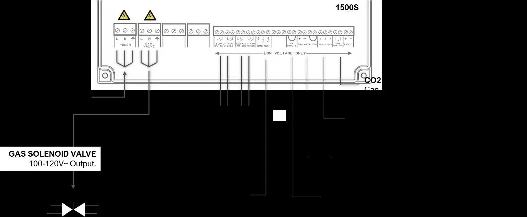
- Gas Solenoid Valve Output: 110-120V AC output to the solenoid valve.
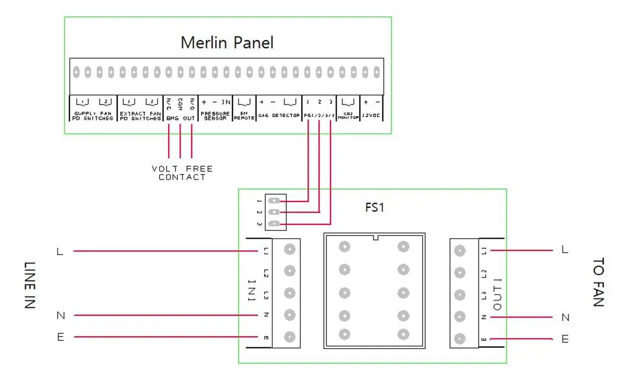
- Fans: Connect external air pressure switches or current monitors to the Supply & Extract Fan terminals. If only one fan is used, leave factory-fitted links in the unused terminals.
- BMS Output: Volt-free connections (NO/COM/NC) for Building Management Systems.
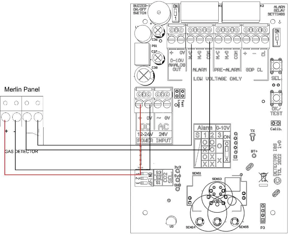
- Gas Detectors: Connect according to the specific detector manual. If no detector is used, leave the factory-fitted link in place.
- EM Remote: For remote emergency shut-off buttons. Linked out by default.
Switch Settings
The circuit board contains DIP switches for system configuration:
- BMS SEL: Set to OFF (default) to signal the BMS when gas is on/off. Set to ON to signal the BMS when high gas levels are detected.
- EM SEL: Set to OFF (default) to shut down fans and gas supply upon emergency shut-off. Set to ON to leave fans running and shut off gas only.
Operation
- First Power Up: Connect mains power, turn on connected fans, and turn the key switch to ON.
- Emergency Shut Off: Located on the front panel. When activated, it cuts off gas and electrics. The system must be reset and restarted after activation.
- LED Indicators:
- Gas On: Indicates the gas valve is open.
- Supply/Extract Fans: Illuminated when running. Flashing indicates a fault. If flashing for >20 seconds, gas will shut off.
- Fan Fault: Illuminates red if a ventilation fault is present for >20 seconds.
- EM Stop: Illuminates if an emergency shut-off button is pressed.
- Gas Detected/CO2 High: Illuminates if high gas levels are detected.
CO2 Mode
This mode allows access to the gas supply in the event of a fan failure. If the Fan Fault LED is red, press the CO2 Mode button for 5 seconds. The system will monitor CO2 levels and allow the gas valve to open for 8 hours, provided CO2 levels are safe. The system must be restarted after 8 hours.
Maintenance
- Regularly remove dust and debris from the outer enclosure using a slightly damp cloth.
- Never spray aerosols (air fresheners, hair spray, paint) near gas detecting devices.
- Never paint the device.
- It is recommended that connected detectors are inspected and serviced annually.
Practical help
Common problems
Fan fault LED is flashing
Check if the supply or extract fans are running. If the fault persists for more than 20 seconds, the gas supply will shut off.
Gas valve will not open
Ensure the ventilation system is proven to be working and the key switch is in the ON position.
CO2 Mode button does not work
CO2 Mode is only available when the Fan Fault LED is illuminated. It will be permanently disabled if no CO2 monitoring device is connected.
Panel beeps on power up
If no CO2 monitor or other device is connected to the 12V DC output, the panel will beep and the CO2 LED will flash to indicate the terminal is disabled.
Before use
- Verify mains power is 110-120V AC.
- Ensure all wiring connections are secure and segregated.
- Check that factory-fitted links are removed only if necessary (e.g., if using detectors/fans).
- Confirm DIP switch settings (BMS SEL, EM SEL) match your installation requirements.
- Ensure the emergency shut-off button is accessible.
Specs in practice
- Mains Electrical Power Input
- 110-120VAC required for operation.
- Internal Fuse
- 3.15A rating.
- Operating Temperature
- 32–104°F (0-95%RH Non-Condensing).
- Audible Alarm Buzzer
- 65 dB at 300mm distance.
Images and diagrams
- Typical Installation Arrangement: Shows connections for power, solenoid valve, fans, BMS, and detectors.
- Connecting Gas Detector: Wiring diagram for standard gas detectors.
- Connecting Gas Detector TFT: Wiring diagram for TFT model detectors.
- Fan Switches: Wiring diagram for connecting FS1/FS2 fan switches.
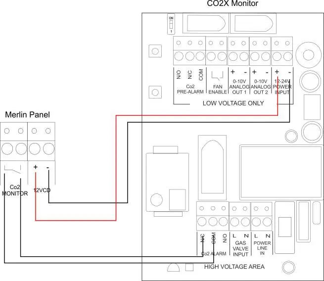
- CO2 Monitor: Wiring diagram for connecting CO2X monitor.
Model compatibility
- Compatible with carbon dioxide, natural gas, carbon monoxide, and LPG sensors.
- Works with Merlin FS1 or FS2 fan switches (sold separately).
- Can be integrated with fire alarm systems.

Manual page author
Emily Carter
User documentation editor
Prepares concise manual descriptions and highlights the most useful setup, operation, and maintenance information for readers.