Industrial / Gas Interlock Systems
User Manual for AGS Merlin Gas Detector i-S
Comprehensive installation, operation, and maintenance guide for the AGS Merlin Gas Detector i-S. Includes wiring diagrams, alarm settings, bump test procedures, and safety guidelines for refrigerant gas monitoring.
Table of contents
Manual images
Click an image to enlargeQuick Guide from the Manual
The AGS Merlin Gas Detector i-S is designed for monitoring refrigerant gases (134a, 407c, 410a, 417a, 32). The device is shipped pre-calibrated. Upon installation, it is recommended to perform a bump test to ensure the system is functioning correctly. The device requires a continuous power supply (12-24Vdc or 24Vac) and should be installed by a licensed contractor. The sensor has an expected lifetime of 10 years.
Installation and Mounting
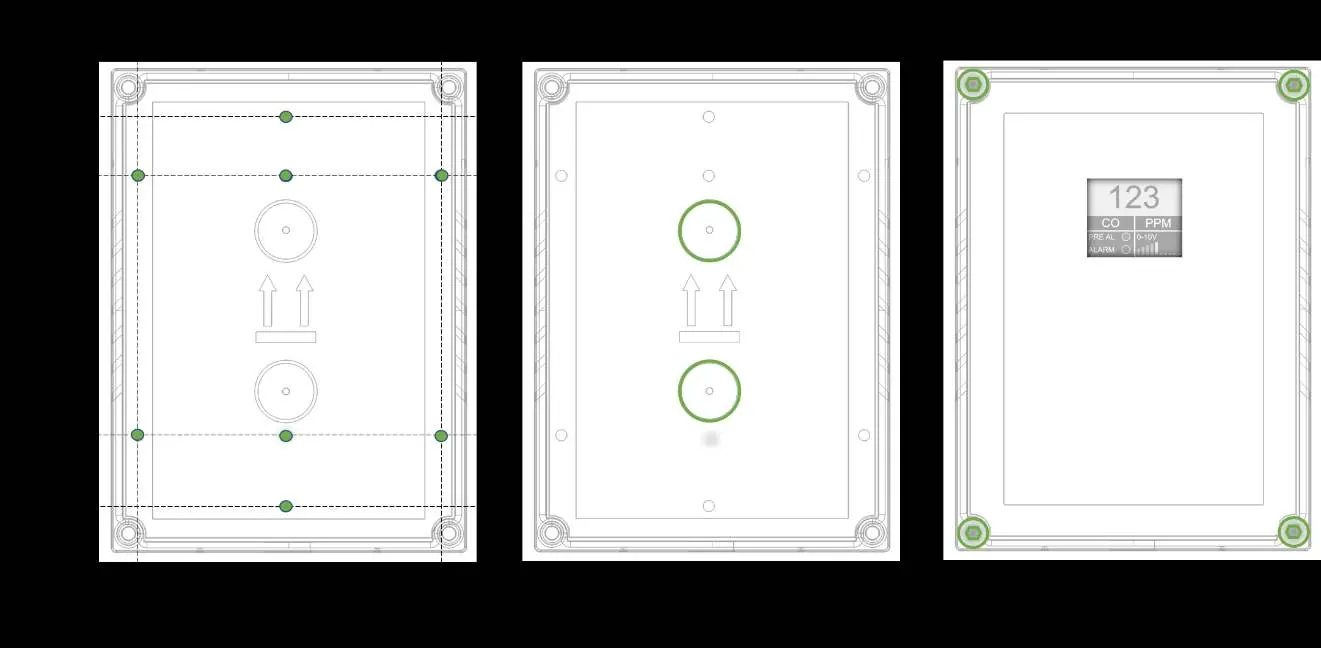
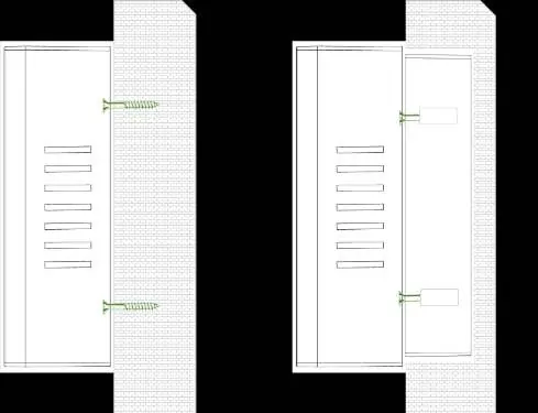
The detector is designed for surface mounting or installation on a 1-gang or 2-gang electrical box. Ensure the wall surface is flat to prevent base distortion. The unit should be mounted where gas is most likely to accumulate, considering the density of the target gas (e.g., low level for heavy gases, high level for light gases). Ensure the rear base is installed in the correct orientation as indicated by the arrows on the base.

Wiring and Connections
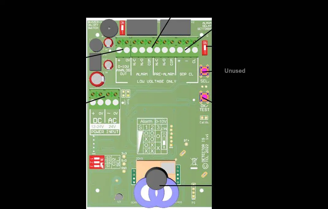
The circuit board features pluggable terminals for easy connection. Power can be provided via 12-24Vdc or 24Vac. The board includes specific terminals for power input, alarm relays, and a 0-10V analogue output for external fan speed controllers. A disconnector is required for the 24V supply. Ensure all wiring is restrained to prevent accidental loosening.

Operation
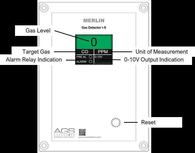
Upon connecting power, the detector enters a 60-second warmup phase. The device features a TFT screen displaying gas levels. Alarm states are indicated by color changes on the screen (Green: Normal, Yellow: Pre-Alarm, Red: Main Alarm). If the alarm relay is latched, a red dot will appear on the screen. To reset the alarm, press and hold the touch sensor for approximately 3 seconds.
Maintenance and Bump Testing
Regular maintenance is required to ensure sensor accuracy. Clean the outer enclosure with a slightly damp cloth; never use detergents, solvents, or aerosols near the device. A 'Bump Test' should be performed every 12-18 months to verify the sensor's response to gas. This involves exposing the sensor to a known concentration of the target gas that exceeds the alarm threshold. If the system fails to trigger an alarm during this test, it must not be used until serviced.
Specifications
The detector operates on 12-24Vdc or 24Vac with a maximum power consumption of 1.8W. It provides dry contact relay outputs (1A switching current). The operating temperature range is -10°C to 50°C. The sensor measuring range is 100-5000ppm, with a pre-alarm at 500ppm and a main alarm at 1000ppm.
Practical help
Common problems
Device in alarm state
Check gas levels. If the alarm is latched, reset by pressing and holding the touch sensor for ~3 seconds.
Sensor sensitivity decline
Avoid exposure to silicon compounds, alcohol, corrosive gases, or aerosols. Ensure the sensor is not painted or covered.
Relay not triggering
Verify wiring connections and ensure the 'Alarm Relay Setting Switch' is configured correctly.
Before use
- Verify the target gas matches the detector model (134a, 407c, 410a, 417a, or 32).
- Ensure power supply is 12-24Vdc or 24Vac.
- Confirm the mounting surface is flat and the unit is oriented correctly.
- Ensure the area is free from contaminants like silicon or alcohol vapors.
- Perform a bump test after installation to validate system response.
Specs in practice
- Relay Output
- 1A switching current (resistive load) @ 24V AC/DC
Images and diagrams
- Circuit board layout showing power input, relay terminals, and buzzer switch.
- Wiring diagrams for standalone power and Merlin controller integration.
Model compatibility
- Compatible with refrigerant gases: 134a, 407c, 410a, 417a, 32.
- Not intended for use in potentially explosive atmospheres.

Manual page author
Michael Turner
Technical manual editor
Reviews PDF manuals for structure, safety notes, and practical product details so readers can find the right information quickly.