Industrial / Motor Control
User Manual for Allen-Bradley 100L-C20 Lighting Contactor
Quick guide for the Allen-Bradley 100L-C20 Lighting Contactor. Includes installation requirements, wiring specifications, load ratings, and safety warnings.
Table of contents
Manual images
Click an image to enlargeQuick Guide
The Allen-Bradley 100L-C20 is a lighting contactor designed for industrial electrical applications. This document provides essential installation, wiring, and safety information. Always disconnect the power source before performing any installation or maintenance tasks. Note that this device is not suitable for isolation as defined in IEC 60947-1.
Safety Warnings
- Electrical Shock Hazard: Disconnect power before installing or servicing.
- Environment: In environments with a risk of contamination or aggressive emissions, the device must be installed in a suitable enclosure.
- Operation: Do not operate the device manually.
Installation and Mounting
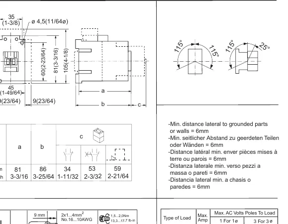
Ensure a minimum lateral distance of 6mm to grounded parts or walls. The device is designed for standard mounting configurations. Refer to the provided dimensional diagrams for exact spacing requirements.
Wiring Specifications
Use 75°C Copper (Cu) wire only. Ensure proper torque settings to prevent loose connections.
- Main Terminals: Use Pozidriv No. 2 screwdriver. Torque: 1.5-2.0 Nm (13.3-17.7 lb-in). Wire capacity: 2x1...4mm² or 2x1.5...6mm² (16-10 AWG).
- A1/A2 Terminals: Use Pozidriv No. 2 screwdriver. Torque: 1-1.5 Nm (8.9-13 lb-in). Wire capacity: 1x1...2.5mm² or 2x1...2.5mm² (16-12 AWG).
Technical Data and Load Ratings
The device is suitable for use on circuits capable of delivering a maximum of 5000 rms Sym. A.
- Tungsten or Ballast: 20A (277V / 480/277V) or 15A (347V / 600/347V).
- General Use Resistance: 30A (600V).
- DC Load: 20A 250V DC Max (with 3 poles in series).
- Fuse/Breaker: Max 90A Fuse (600V) or 50A Circuit Breaker (480V).
Manufacturer information
Allen-Bradley
Practical help
Common problems
Device not operating correctly
Ensure the device is not being operated manually and that power is connected correctly. Check for contamination in the environment.
Installation environment concerns
If the environment contains aggressive emissions or contamination, install the contactor in a suitable protective enclosure.
Before use
- Disconnect power source before installation or servicing.
- Verify the environment is free from aggressive emissions or use an enclosure.
- Ensure a minimum lateral clearance of 6mm to grounded parts.
- Use 75°C Copper wire only.
- Use a Pozidriv No. 2 screwdriver for terminal connections.
- Verify wire gauge matches the terminal requirements (16-10 AWG or 16-12 AWG).
Specs in practice
- Min. lateral distance
- 6mm clearance required to grounded parts or walls.
- Main Terminal Torque
- 1.5-2.0 Nm (13.3-17.7 lb-in) for secure connection.
- A1/A2 Terminal Torque
- 1-1.5 Nm (8.9-13 lb-in) for control connections.
- Short Circuit Rating
- Suitable for circuits delivering max 5000 rms Sym. A.
Images and diagrams
- The dimensional diagram provides measurements in mm and inches for mounting.
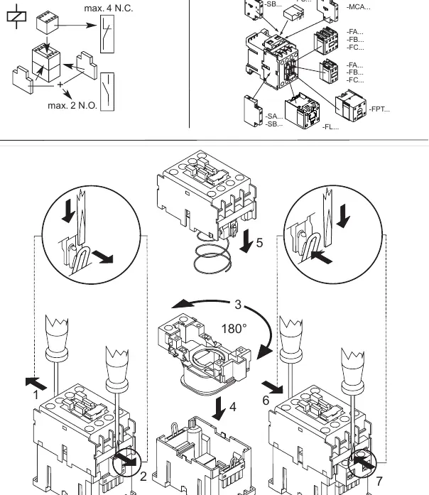
- The wiring diagram illustrates the connection points for A1/A2 and main load terminals.
- The accessory diagram (steps 1-7) shows the sequence for attaching auxiliary components.
Model compatibility
- Not suitable for isolation as defined in IEC 60947-1 Ed 5.2 clause 7.1.7.
- Suitable for use on circuits capable of delivering max 5000 rms Sym. A.

Manual page author
Emily Carter
User documentation editor
Prepares concise manual descriptions and highlights the most useful setup, operation, and maintenance information for readers.