Industrial / Motor Control
Maintenance and Installation Instructions for Allen-Bradley 1102C Vacuum Contactor
Comprehensive maintenance and installation guide for the Allen-Bradley 1102C Vacuum Contactor. Includes step-by-step procedures for coil replacement, contact life measurement, wiring diagrams, and safety testing.
Table of contents
Manual images
Click an image to enlargeQuick Guide
The Allen-Bradley 1102C Vacuum Contactor is a high-performance industrial component. Before performing any installation or maintenance, always disconnect the power source to prevent electrical shock. The contactor can be mounted in any plane, but if mounted in a non-horizontal plane, the top must point up to ensure the label is right-side up. Critical maintenance includes checking contact life using a .010" gauge and performing routine integrity tests.
Installation
Proper installation is essential for reliable operation:
- Mounting: Use the hardware specified in the diagrams. Loosely install the four mounting bolts, then torque them to 50-75 lb-inches. Ensure the mounting surface is flat; use shims if the surface is twisted to prevent phase-to-phase discrepancies.
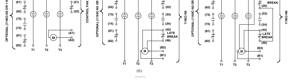
- Wiring: Connect control wires to terminals A1 and A2 using #18 to #12 gauge 75°C copper wire, torqued to 7 lb-inches. Connect line and load conductors to main terminals using 75°C copper cable, torqued to 132 lb-inches.
- Verification: Check all connections for mechanical integrity before energizing.
Coil Replacement
If the coil requires replacement, follow these steps:
- Disconnect all power and control wiring.
- Remove the contactor from its location and place it on a benchtop.
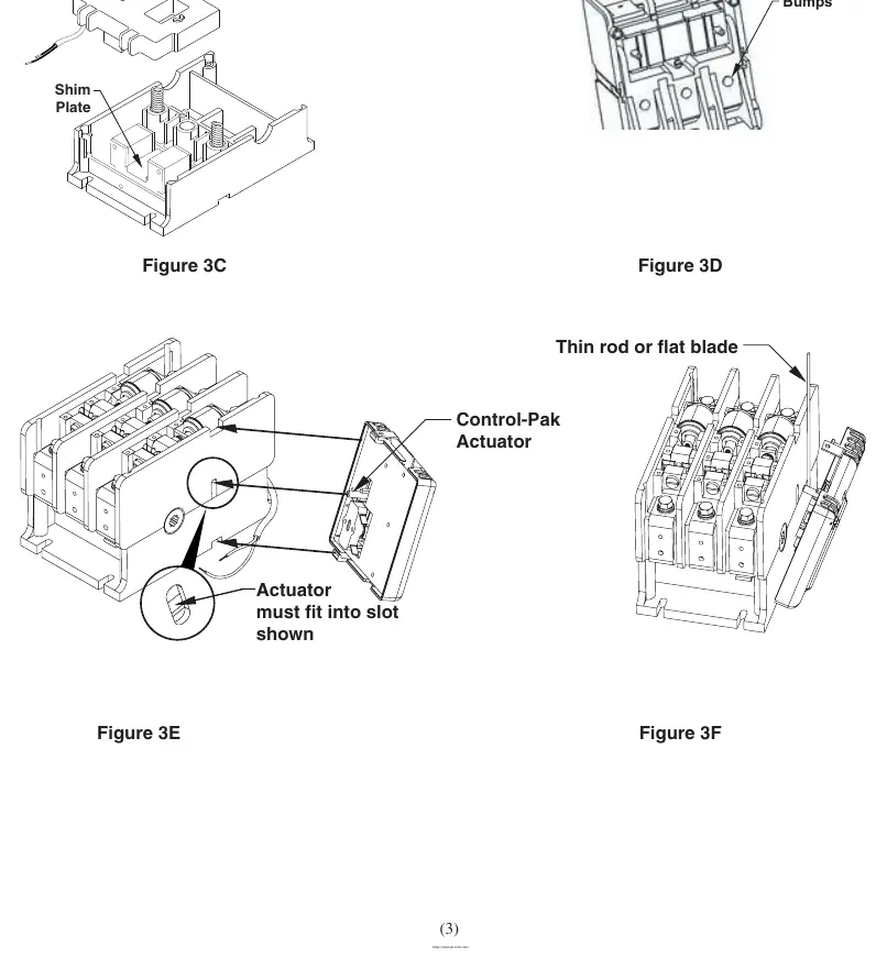
- Remove the cover and Control-Pak.
- Remove the six screws securing the Upper Housing to the Lower Housing (remove outer screws first, then center screws). Note: Removing center screws releases the Return Springs.
- Replace the coil, ensuring the Shim Plate remains in position.
- Reassemble in reverse order, ensuring Return Springs are seated on the outer bumps of the Contact Operator.
- Tighten housing screws in a diagonal pattern to 12 lb-inches.
- Reinstall the Control-Pak, ensuring the actuator fits into the slot.
Contact Life Over-Travel Measurement
To determine remaining electrical life:

- De-energize the contactor.
- Remove the Phase Cover to access the inspection area.
- With the contactor closed, attempt to insert a standard .010" wire gauge into the gap.
- If the gauge fits, sufficient life remains for approximately 100,000 operations.
- If the gauge cannot be inserted, the contact life is exhausted, and the contactor must be replaced.
Cleaning and Maintenance
Preventative maintenance should be performed every twelve months:
- Keep the device free of dirt and dust.
- Verify mechanical operation and freedom of movement.
- Clean molded parts and tracking surfaces by vacuuming or wiping. Do not use compressed air.
- Ensure all power and control terminals remain tight.
Vacuum Interrupter Integrity Test
A high potential test should be performed annually or after exposure to fault conditions:
- Use a 50/60 Hz test set capable of 20 kV.
- Personnel must stay at least ten feet away from the interrupter and test cables.
- With the contactor open, connect the test set across the interrupter terminals.
- Slowly raise the voltage to 10 kV and hold for 15 seconds.
- Leakage current must not exceed 5 mA. If the 10 kV level cannot be reached, the interrupter must be replaced.
Manufacturer information
Allen-Bradley
Practical help
Common problems
Contact life exhausted
If a .010" gauge cannot be inserted into the gap when the contactor is closed, the contactor must be replaced.
Coil failure suspected
Check for secondary damage that may render the contactor non-repairable before attempting coil replacement.
High contact resistance
If resistance exceeds 400 micro-ohms, perform a high potential test to verify interrupter condition.
Mounting surface is twisted
Use shims to correct the condition; end-to-end twist can cause phase-to-phase discrepancies.
Before use
- Check packing list against order to ensure all components are received.
- Examine shipping box for damage before unpacking.
- Ensure power source is disconnected before installation or servicing.
- Verify mounting surface is flat; use shims if necessary.
- Check all electrical connections for tightness before energizing.
Specs in practice
- 50-75 lb-inches
- Torque specification for mounting bolts.
- 132 lb-inches
- Torque specification for main terminal bolts.
Images and diagrams
- Figure 1 & 2: Shows terminal locations and mounting hardware assembly.
- Figure 3A-3F: Illustrates the step-by-step disassembly and reassembly for coil replacement.
- Figure 7A-7C: Details the replacement procedure for the vacuum interrupter phase assembly.
- Figure 8: Shows the inspection area for the contact life over-travel measurement.
Model compatibility
- 1195C-N3/N4/N5/N6 auxiliary kits are available for specific contact arrangements.
- Ensure Control-Pak voltage matches the coil kit voltage.
- 1102C-VB2 is the replacement kit for the 200A vacuum interrupter phase assembly.

Manual page author
David Miller
Documentation analyst
Organizes user manual content into clear summaries, with attention to model details, product context, and everyday usability.