Industrial / Electrical
S+S Regeltechnik RHEASREG WFS Vane Switch Instruction Manual
Quick guide for the S+S Regeltechnik RHEASREG WFS mechanical vane switch. Includes installation requirements, flow monitoring settings, wiring diagrams, and technical specifications.
Table of contents
Manual images
Jump to the sectionQuick guide from the manual
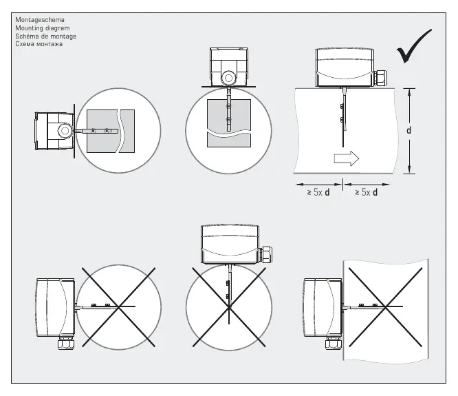
The RHEASREG WFS is a mechanical vane switch designed for flow monitoring of gaseous, non-aggressive media in air conditioning ducts, ventilation systems, or heating registers. Installation is only permitted in horizontal air ducts. A damping section of at least 5 times the pipe diameter must be maintained before and after the installation point to prevent turbulence.

Installation and Mounting
The device must be mounted so that the airflow acts directly on the paddle and the measurement is not distorted by the paddle's own weight. Ensure the device is installed in a horizontal position as shown in the mounting diagrams.
Flow Rate Adjustment
The switch is factory-adjusted to the minimum default value. If wind speeds exceed 5 m/s, the paddle must be cut at the marked positions to prevent breakage, which will increase the default switching values. The range adjusting screw allows for continuous adjustment of the minimum values up to the maximum specified range.
Wiring
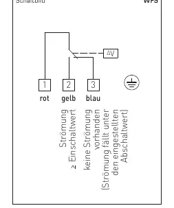
The device features a potential-free changeover contact. Contact 1-3 opens when the flow rate drops below the set value, while contact 1-2 closes simultaneously and can be used as a signal contact.
Technical Data
- Switching capacity: 15 (8) A; 24...250 V AC (at 24 V AC min. 150 mA)
- Protection type: IP 65 (EN 60529)
- Housing temperature: -40 to +85 °C
- Operating difference: ≥ 1.5 m/s
- Cable connection: M20 x 1.5 plastic cable gland (8-13 mm diameter)
Safety and Maintenance
Installation and commissioning must be performed by qualified personnel only. The device must be connected in a dead-voltage state. Avoid installing near heat sources or in direct sunlight. Shielded cables are recommended to prevent interference. The device is not intended for safety-critical monitoring or emergency stop functions.
Manufacturer information
S+S Regeltechnik GmbH
Practical help
Common problems
Paddle breakage at high wind speeds
If wind speeds exceed 5 m/s, the paddle must be cut at the marked positions to prevent damage.
Unstable switching due to turbulence
Ensure a damping section of at least 5 times the pipe diameter is present before and after the installation location.
Measurement distortion
Ensure the device is mounted in a horizontal air duct so that the paddle is not affected by its own weight.
Before use
- Verify the installation location is in a horizontal air duct.
- Ensure a damping section of ≥ 5x pipe diameter exists before and after the sensor.
- Check if wind speed exceeds 5 m/s; if so, cut the paddle at marked spots.
- Ensure electrical connections are made while the device is in a dead-voltage state.
- Use shielded cables to avoid voltage induction.
Specs in practice
- Switching capacity
- Maximum electrical load the internal microswitch can handle (15A resistive, 8A inductive).
- Operating difference
- The minimum change in flow velocity required to trigger the switch state change (≥ 1.5 m/s).
Images and diagrams
- The wiring diagram shows terminals 1, 2, and 3.
- Contact 1-3 opens when flow drops below the set value.
- Contact 1-2 closes when flow drops below the set value, acting as a signal contact.
- The mounting diagram illustrates the required 5x diameter distance before and after the sensor.
Model compatibility
- Suitable for gaseous, non-aggressive media.
- Not for use as an emergency stop switch.
- Not for safety-relevant monitoring of persons.

Manual page author
David Miller
Documentation analyst
Organizes user manual content into clear summaries, with attention to model details, product context, and everyday usability.