Lighting / Outdoor Lighting
Installation Instructions for Anolis DIVINE 60 UV Luminaire
A comprehensive installation guide for the Anolis DIVINE 60 UV luminaire. This manual covers electrical wiring, cable gland installation, mounting options, and head position adjustments.
Quick answers from the manual
Quick answer
- The Anolis DIVINE 60 UV must be installed by a qualified electrician. It requires a 5-cored cable (Flamar Li9YC11Y) for power and DMX. Ensure the unit is grounded and cable glands are sealed with recommended LOCTITE products. p. 2, 3, 4
Key actions
- Install cable glands p. 4
- Connect power and DMX p. 3
- Adjust head position p. 6
Problems and fixes
Water-tight seal failure
Failure to properly install cable glands will result in failure of the water tight seal.
p. 4Technical specifications
| Parameter | Value | Meaning | Pages |
|---|---|---|---|
| Cable Gland M20x1.5 | Wrench size 24 | Required tool size for installation | p. 4 |
| Cable Gland M12x1.5 | Wrench size 16 | Required tool size for installation | p. 4 |
Where to find it in the PDF
- Installation Instructions p. 1, 2, 3, 4
Table of contents
Manual images
Click an image to enlargeQuick Guide from the Manual
The Anolis DIVINE 60 UV is a professional lighting fixture that must be installed by a qualified electrician in accordance with all national and local electrical and construction codes. This device is a Class 1 product and must be properly grounded.
Installation Overview
The installation process involves preparing the cable glands, accessing the junction box, wiring the power and data connections, and mounting the fixture using the appropriate hardware.
Cable Gland Installation
Proper installation of cable glands is critical to maintain the water-tight seal. Use wrench size 24 for M20x1.5 glands and wrench size 16 for M12x1.5 glands. It is recommended to apply LOCTITE 5331 on the plastic holder and LOCTITE 577 on the thread of the gland body.
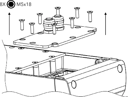
Junction Box Access
To access the junction box, remove the cover by unscrewing the 8x M5x18 screws. When closing the junction box, ensure the thread is clean and functional, and tighten the screws to 7 Nm.
Electrical Connection
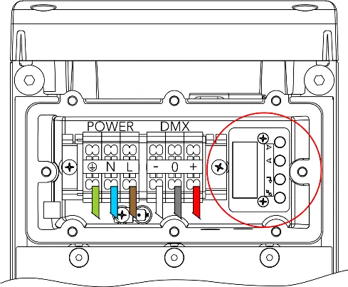
Use a 5-cored cable (Flamar Li9YC11Y) for both power and DMX control. The cable consists of 3 cores for power supply and 2 shielded cores for DMX connection.
- Power Connection Strip Length: 9mm
- Data Connection Strip Length: 7mm
Color Coding:
- Brown: Power L
- Blue: Power N
- Yellow/Green: Ground
- White: Data - (D-)
- Red: Data + (D+)
- Shielding: Data Ground (0V)
Mounting Options
The fixture supports multiple mounting configurations:
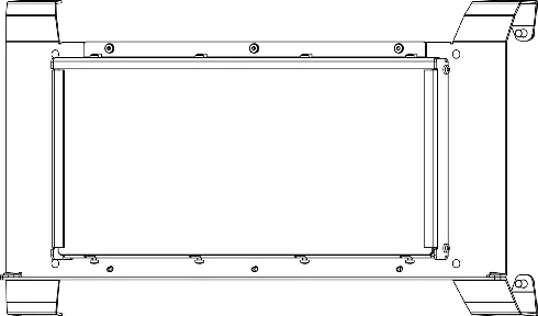
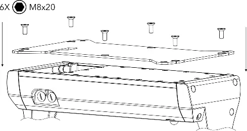
- Surface Mount Adaptor: Mount the adaptor using 6 mounting screws.
- Rubber Feet: Mount the pair of rubber feet using 4 screws.
- C-Clamp Adaptor: Mount the adaptor using 5 screws.
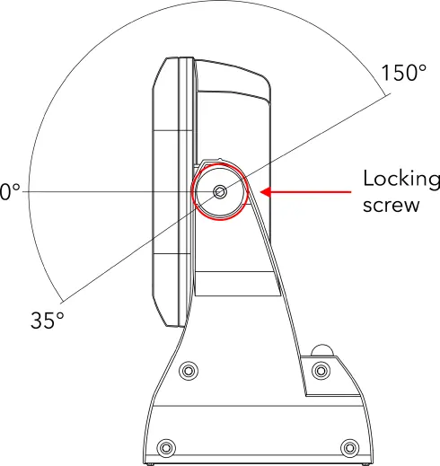
Head Position Adjustment
The head position can be adjusted by releasing the locking screw on each side of the fixture. Once the desired angle is achieved, tighten the locking screws on both sides to secure the position.
Manufacturer information
Anolis
Practical help
Common problems
Water-tight seal failure
Ensure cable glands are installed individually and correctly. Apply LOCTITE 577 on the thread of the gland body and LOCTITE 5331 on the plastic holder.
Before use
- Ensure installation is performed by a qualified electrician.
- Verify the device is grounded (Class 1).
- Use a 5-cored cable (Flamar Li9YC11Y).
- Check that wrench sizes 24 and 16 are available for cable glands.
- Ensure mounting surface is appropriate for the chosen adaptor.
Specs in practice
- Power Connection Strip Length
- 9mm
- Data Connection Strip Length
- 7mm
- Junction Box Torque
- 7 Nm
Images and diagrams
- Wiring diagram illustrates the terminal block connections for Power (L, N, Ground) and DMX (-, 0, +).
- Head position adjustment allows for a range of movement secured by locking screws.
Model compatibility
- Requires 5-cored cable Flamar Li9YC11Y.
- Compatible with Surface Mount Adaptor, Rubber Feet, and C-Clamp Adaptor.

Manual page author
Emily Carter
User documentation editor
Prepares concise manual descriptions and highlights the most useful setup, operation, and maintenance information for readers.