Lighting / Fixtures
Installation Instructions for Anolis ArcSource Outdoor 16MC Integral
Comprehensive installation guide for the Anolis ArcSource Outdoor 16MC Integral lighting fixture. Includes detailed mounting procedures for various surfaces (yoke, floor stand, land spike, tenon, pole clamp), electrical connection...
Quick answers from the manual
Quick answer
- The Anolis ArcSource Outdoor 16MC Integral is a lighting fixture that requires installation by a qualified electrician. It supports various mounting methods including yoke, floor stand, land spike, tenon adaptor, and pole clamp, and requires specific wiring procedures for power and DMX connections. p. 1, 2, 7, 8
Key actions
- Mounting the fixture p. 2, 3, 4, 5
- Connecting power and DMX p. 7, 8
First start
- Ensure the fixture is installed by a qualified electrician and properly grounded. p. 2
Problems and fixes
Water-tight seal failure
Ensure cable glands are installed individually and properly with the specified thread sealants.
p. 9Technical specifications
| Parameter | Value | Meaning | Pages |
|---|---|---|---|
| Power Connection (Strip length) | 9 mm | Length to strip for power wires. | p. 8 |
| Data Connection (Strip length) | 7 mm | Length to strip for data wires. | p. 8 |
Where to find it in the PDF
- Mounting p. 2, 3, 4, 5
- Connection p. 7, 8
- Accessories p. 9, 10, 11
Table of contents
Manual images
Click an image to enlargeQuick guide from the manual
This document provides installation instructions for the Anolis ArcSource Outdoor 16MC Integral. Important: The fixture must be installed by a qualified electrician in accordance with all national and local electrical and construction codes. This device is a Class 1 product and must be grounded.
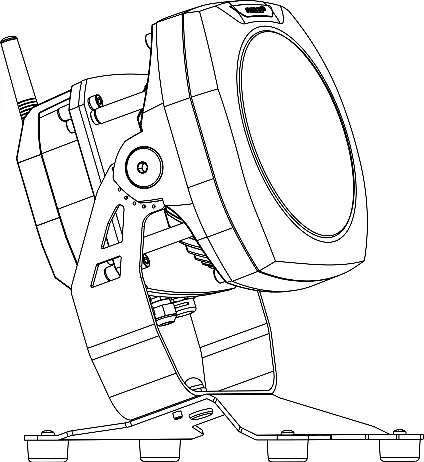
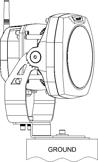
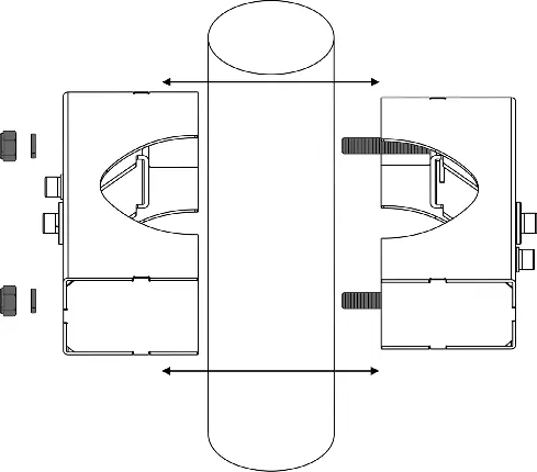
Mounting the fixture
The fixture supports multiple mounting configurations:
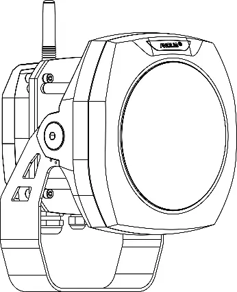
- Using Yoke: Mount via suitable holes on a secure, non-flammable surface. Fasten the yoke with three screws. Use an Allen key 6 to release the M8 tilting lock on each side to adjust the LED module tilt (+35°/-90°).
- Using Floor Stand: Mount the floor stand to the surface using 4 holes (9mm or 7mm diameter). Secure the luminaire to the stand using the provided nut and washer.
- Using Land Spike: Insert the spike perpendicularly into the ground. Mount the luminaire to the spike using two M8x20 screws with washers and spring washers.
- Using Tenon Adaptor: Slide the adaptor onto a tenon (e.g., metal post) and fasten with three screws. Mount the luminaire to the adaptor using two M8x25 screws with washers and spring washers.
- Using Pole Clamp: Disassemble the clamp, mount it to the pole, and tighten the nuts. Attach the luminaire yoke to the clamp using two M8x25 screws with washers and spring washers.
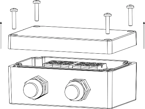
Electrical connection
Connections are made via the Junction Box:
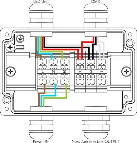
- Single luminaire: Connect DMX IN and Power cable to the junction box, then connect the power/data cable from the box to the luminaire.
- Multiple luminaires (Daisy chain): Use power/data cables between junction boxes. Note that the connection scheme changes after the first junction box.
- Wiring: Follow the provided color-coding charts for EU (Brown/Blue/Green-Yellow) and US (Black/White/Green) standards. Strip power connections to 9mm and data connections to 7mm.
Cable gland installation
Use a size 24 wrench for M20x1.5 cable glands. Install glands individually. Apply Loctite 5331 thread sealant on the plastic holder and Loctite 577 thread locking compound on the gland body before assembly. Failure to install correctly will result in the failure of the water-tight seal.
Installation of accessories
Accessories like the Top Hat and Half Top Hat are installed by removing the rear screws of the luminaire, sliding the accessory into place, and fastening it with the appropriate screws (M6x12 or M3x6) and lockwashers as specified in the diagrams.
Manufacturer information
Anolis
Practical help
Common problems
Water-tight seal failure
Ensure cable glands are installed individually and properly with the specified thread sealants (Loctite 5331 and 577).
Mounting instability
Ensure the mounting surface is secure and non-flammable, and use appropriate fasteners for the specific surface type.
Before use
- Ensure installation is performed by a qualified electrician.
- Verify the mounting surface is secure and non-flammable.
- Confirm the device is properly grounded (Class 1).
- Check that all cable glands are tightened correctly.
- Verify the correct wiring color code for your region (EU/US).
Specs in practice
- M8 tilting lock
- Used to adjust the tilt of the LED module in a range of +35°/-90°.
- Cable gland M20x1.5
- Requires a size 24 wrench for installation.
- Junction Box screws
- M4x20 screws are used to secure the junction box cover.
Images and diagrams
- Wiring diagrams illustrate the specific color-coded connections for single and daisy-chained units.
- Mounting diagrams show the exact screw sizes (e.g., M8x20, M8x25) required for each mounting method.
Model compatibility
- Tenon Adaptor supports diameters 63-80 mm and 80-106 mm.
- Pole Clamp supports diameters 63-80 mm and 80-105 mm.

Manual page author
Michael Turner
Technical manual editor
Reviews PDF manuals for structure, safety notes, and practical product details so readers can find the right information quickly.