Smart Home / Smart Relays
User Manual for AURATON Switch ONE 1-Channel Smart Relay Module
Quick guide for the AURATON Switch ONE 1-channel smart relay module. Includes installation instructions, wiring diagrams, technical specifications, and pairing procedures.
Table of contents
Manual images
Click an image to enlargeQuick guide from the manual
The AURATON Switch ONE is a 1-channel executive module designed to control electrical devices. Key requirements for installation include an electrical box with a minimum depth of 60 mm and an external 10A circuit breaker. The device supports both AC (60-240V) and DC (12-30V) power sources and requires an AURATON Box for remote control functionality.
Device description
The device features three main components:
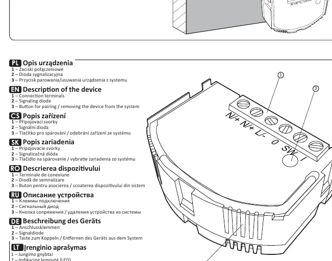
- Connection terminals: For power, load, and switch wiring.
- Signaling diode: Indicates device status.
- Button: Used for pairing or removing the device from the system.
Installation and wiring
The device must be installed in an installation box with a minimum depth of 60 mm. Ensure the power is disconnected before starting installation.
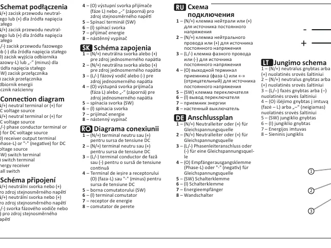
Wiring terminals:
- 1 & 2 (N/+): Neutral terminal or (+) for DC voltage source.
- 3 (L/-): Phase conductor terminal or (-) for DC voltage source.
- 4 (O): Receiver output terminal (Phase-L) or (-) for DC voltage source.
- 5 & 6 (SW): Switch terminals for connecting a wall switch.
- 7: Energy receiver.
- 8: Wall switch.
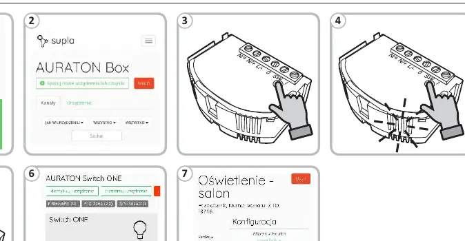
Pairing
To pair the AURATON Switch ONE with the AURATON Box, follow the instructions provided in the AURATON Box application. Use the button on the device to initiate the pairing process.
Technical specifications
- Power supply: 60-240V AC (50-60 Hz) or 12-30V DC.
- Max load: Up to 8.6A for resistive load.
- Protection: Requires external 10A circuit breaker.
- Radio frequency: 868.150 MHz; 868.450 MHz.
- Operating range: Approx. 30 m.
- Operating temperature: 0 – 35°C.
- Protection class: IP20.
Safety and disposal
The device is marked with a crossed-out waste bin symbol, indicating it must not be disposed of with household waste. Users are responsible for delivering the device to a designated collection point for electrical and electronic equipment.
Practical help
Common problems
Device not pairing
Ensure the AURATON Box is in range and in pairing mode. Check if the device is correctly powered.
Device not switching
Verify that the external 10A circuit breaker is active and that the load does not exceed 8.6A.
Before use
- Ensure the installation box has a minimum depth of 60 mm.
- Verify the power supply type (12-30V DC or 60-240V AC).
- Ensure the load does not exceed 8.6A (resistive load).
- Have an external 10A circuit breaker ready for installation.
- Confirm compatibility with AURATON Box for remote features.
Specs in practice
- Max Load: 8.6A
- The maximum current for resistive loads. Exceeding this may damage the relay.
- Voltage: 12-30V DC / 60-240V AC
- The device is versatile and supports both low voltage DC and standard mains AC.
Images and diagrams
- Terminals 1 & 2: Neutral (N) or DC (+).
- Terminal 3: Phase (L) or DC (-).
- Terminal 4 (O): Output to the connected electrical device.
- Terminals 5 & 6 (SW): Connection points for the manual wall switch.
Model compatibility
- Requires AURATON Box for internet/remote control features.
- Uses AURA radio protocol.

Manual page author
Michael Turner
Technical manual editor
Reviews PDF manuals for structure, safety notes, and practical product details so readers can find the right information quickly.