HVAC / Thermostats & Controls
Operating Instructions for GIRA 5061 00 1-Gang Switching Actuator
Quick guide for the GIRA 5061 00 1-gang switching actuator. Includes installation, wiring, commissioning via Gira Project Assistant, and technical specifications.
Table of contents
Manual images
Click an image to enlargeQuick guide from the manual
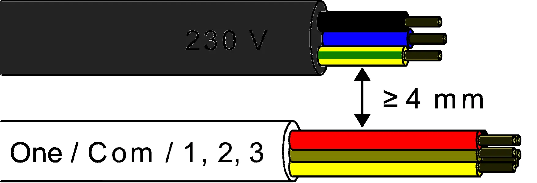
This device is a switching actuator for the Gira One Smart Home system. It is designed for installation in an appliance box and requires commissioning via the Gira Project Assistant (GPA) version 5 or higher. Crucial safety requirement: A minimum distance of at least 4 mm must be maintained between bus conductors and mains voltage cores. Installation must be performed by an electrically skilled person.
Safety instructions
Electrical devices may only be mounted and connected by electrically skilled persons. Failure to follow instructions may result in serious injuries, fire, or property damage. The device is not suitable for disconnection from supply voltage. Do not connect any external voltage to the inputs, as this may damage the device and compromise the SELV potential on the bus line.
Installation and wiring
The device is intended for mounting in an appliance box with dimensions according to DIN 49073. It is recommended to use an electronic device box with a partition wall to separate the bus/extension wires from the mains voltage wires. Ensure adequate cooling and observe the ambient temperature.
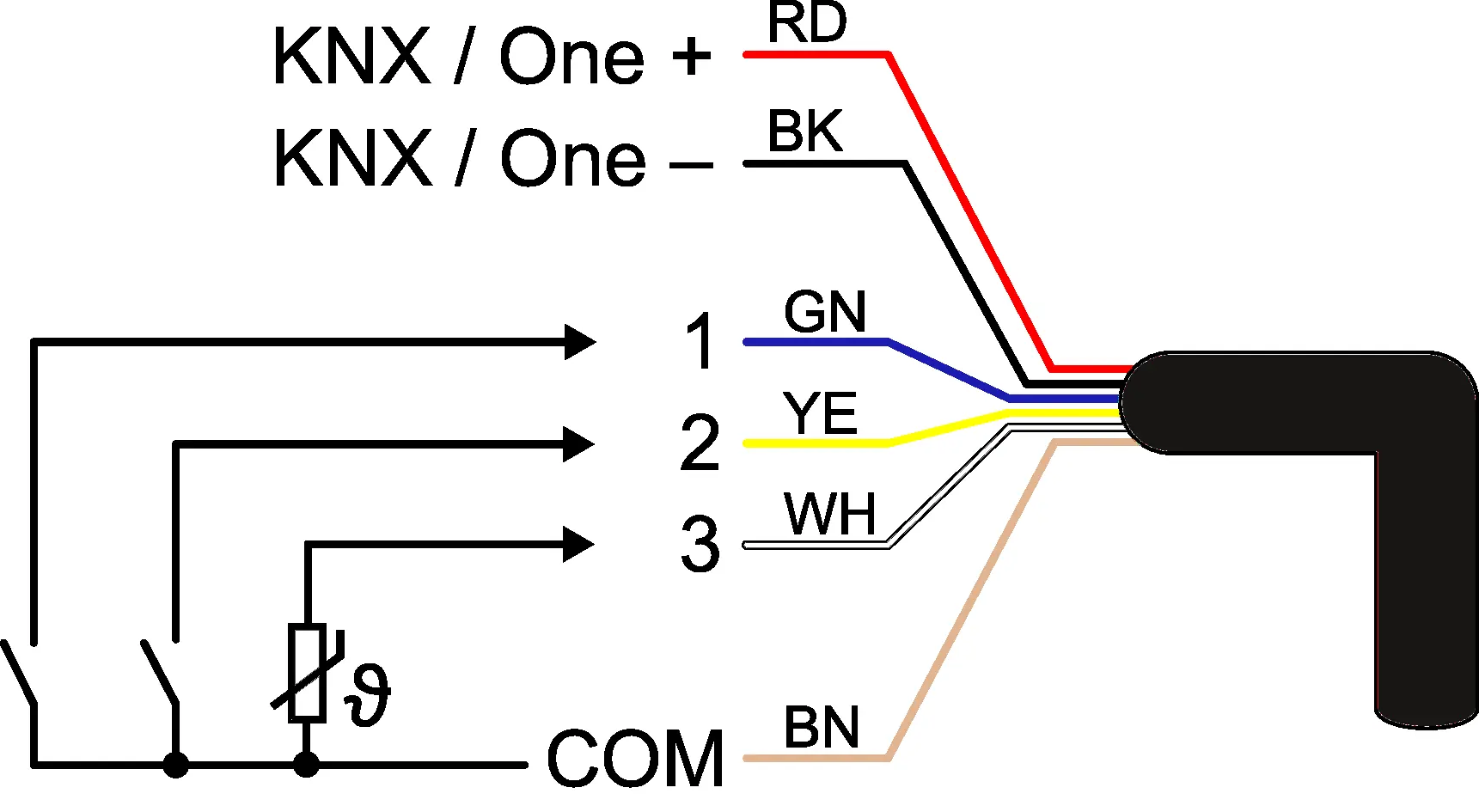

Connect the bus line while observing the correct polarity. Connect the load circuit as specified. If required, connect potential-free contacts, condensation/leakage sensors, or an NTC temperature sensor to the inputs. The COM reference potential must not be connected together with COM connections of other devices.
Commissioning
Commissioning is performed using the Gira Project Assistant (GPA). Before switching on the load, ensure that all relay contacts are open by applying the bus voltage to avoid undefined relay states. Switch on the bus voltage, wait about 10 seconds, and then connect the load circuit.
In the as-delivered state, the output can be operated via the switch at input 1 (ON/OFF). Inputs 2 and 3 have no function until configured via the GPA.
Troubleshooting and reset
Safe-state mode: Stops program execution. To activate: disconnect from bus, wait 10s, press and hold programming button, reconnect to bus, and release button when the programming LED starts flashing slowly.
Master reset: Restores basic device settings. To perform: activate safe-state mode, then press and hold the programming button for more than 5 seconds until the LED flashes quickly. The device will restart after approximately 5 seconds.
Technical data
The device operates on a rated voltage of DC 21 to 32 V (SELV) via the bus. It features a 16 AX switching current capacity. The ambient temperature range is -5 to +45 °C. The device supports various load types, including ohmic, capacitive, motors, and various lamp types (incandescent, halogen, LED, fluorescent).
Practical help
Common problems
Unexpected control of connected loads during commissioning
Ensure all relay contacts are open by applying bus voltage before switching on the load circuit.
Inputs 2 and 3 are not responding
In the as-delivered state, only input 1 is active. Configure inputs 2 and 3 using the Gira Project Assistant (GPA).
Device not functioning or programming LED not responding
Check bus connection and polarity. Ensure the device is not in safe-state mode.
Before use
- Ensure installation is performed by an electrically skilled person.
- Verify a minimum of 4 mm spacing between mains voltage and bus/extension wires.
- Use an appliance box with a fixed partition wall.
- Check bus polarity before connection.
- Ensure relay contacts are open before applying bus voltage.
- Have Gira Project Assistant (GPA) version 5 or higher ready for commissioning.
Specs in practice
- Rated voltage
- DC 21 to 32 V (SELV) supplied via the bus.
- Switching current
- 16 AX (maximum load capacity).
- Ambient temperature
- Operating range is -5 to +45 °C.
Images and diagrams
- Wiring diagram illustrates the connection of the bus (KNX/One) and the three binary inputs.
- Cable spacing diagram highlights the mandatory 4 mm separation between 230V mains and bus/extension cables.
Model compatibility
- Requires Gira Project Assistant (GPA) version 5 or higher.
- Compatible with NTC temperature sensors, condensation sensors, and leakage sensors (sold separately).
- Mounting requires appliance boxes according to DIN 49073.

Manual page author
David Miller
Documentation analyst
Organizes user manual content into clear summaries, with attention to model details, product context, and everyday usability.