HVAC / Air Conditioners
Installation Instructions for Bard 11EER WA Series Wall Mount Air Conditioner
Comprehensive installation and setup guide for the Bard 11EER WA Series wall-mount air conditioner. Includes mounting instructions, wiring diagrams, airflow settings, and troubleshooting for the Refrigerant Leak Detection System (RDS).
Table of contents
Manual images
Click an image to enlargeQuick guide from the manual
This document provides installation and service instructions for the Bard 11EER WA Series wall-mount air conditioner. Key procedures include wall mounting, ductwork connection, electrical wiring, and system startup. The unit uses R-454B refrigerant and includes advanced features like Balanced Climate mode and a Refrigerant Leak Detection System (RDS). Always ensure the unit is installed by trained, experienced technicians in accordance with local and national codes.
Safety Instructions
Warning: This unit contains mildly flammable R-454B refrigerant. Follow all safety precautions, including:
- Maintain a minimum 1/4 inch clearance between the supply air duct and combustible materials in the first 3 feet of ducting.
- Always disconnect remote electric power supplies before servicing.
- Use more than one person to handle the unit due to its weight.
- Do not operate without an earth ground.
- Auxiliary devices that are potential ignition sources (e.g., hot surfaces >700°C) must not be installed in the ductwork.
Installation
Successful installation requires proper site inspection and planning. Ensure the wall is strong enough to support the unit and that service clearances are met.
Wall Mounting
- Prepare the wall by cutting holes for supply and return air as specified in the mounting instructions.
- Install the bottom mounting bracket to help support the unit during installation.
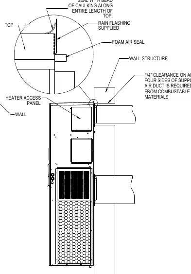
- Apply a liberal amount of caulk to the cabinet side wall mount brackets and the back of the top rain flashing.
- Secure the unit to the wall using field-supplied fasteners through the built-in wall mounting brackets.
- Apply a bead of caulk between the back of the unit top and the front surface of the top rain flashing to prevent water entry.
Ductwork
All ductwork must be properly sized and insulated. Flexible joints should be used to minimize noise transmission. If no return air duct is used, a metallic return air grille with louvers no larger than 5/8 inch is required.
Wiring
Main Power
Verify voltage is consistent with unit specifications. Use copper conductors only. Refer to the unit serial plate for maximum fuse or circuit breaker size.
Low Voltage (24VAC) Connections
- C: 24VAC common (grounded).
- G: Indoor blower input.
- Y1: 1st Stage cooling input.
- Y2: 2nd Stage compressor input.
- B/W1: 1st stage electric heat.
- W2: 2nd stage heat.
- A: Ventilation input.
- D: Dehumidification input.
System Features
Balanced Climate Mode
This mode enhances comfort by reducing indoor airflow and extending run time to improve humidity removal. To enable, remove the Y1-Y2 jumper bar. A 2-stage cooling thermostat is recommended for optimal performance.
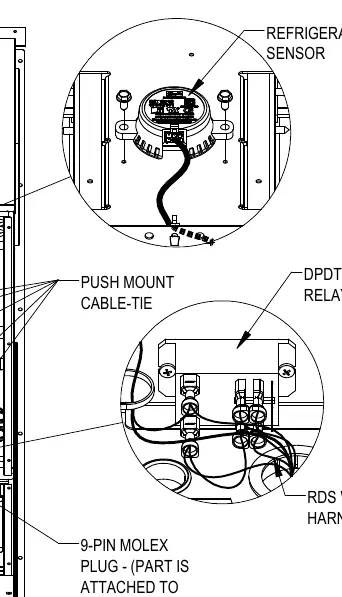
Refrigerant Leak Detection System (RDS)
The RDS monitors for refrigerant leaks. If a leak is detected, the system enters mitigation mode: the indoor blower is activated, compressor and electric heat operation are prohibited, and the 'L' terminal is energized to trigger an alarm.
Service and Maintenance
Troubleshooting ECM Motors
If the motor is running but noisy or not changing speeds, check for programmed delays, ensure control inputs are wired correctly, and verify that all dampers/registers are open. Check external static pressure to ensure it is within limits.
Setting Unit Airflow
The unit has five factory-programmed speed taps. The default speed is the lowest cooling speed. To change speeds, move the orange/black wire on the blower speed terminal block to the desired tap (MED or HI). Refer to the airflow performance graphs for specific CFM values.
Dirty Filter Switch
The switch measures pressure drop across the filter. It is adjustable; the recommended starting point is 0.4 inch W.C. Adjust the knob clockwise to increase the restriction required to activate the switch.
Practical help
Common problems
Compressor will not start
Check if the vent plug or jumper is installed in the vent connection plug. The unit will not operate without one.
Motor not running
Check for proper high voltage and ground at the motor connections. Verify low voltage signal from the thermostat.
System excessively noisy or not changing speeds
Check external static pressure, ensure all dampers/registers are open, and verify motor control wiring.
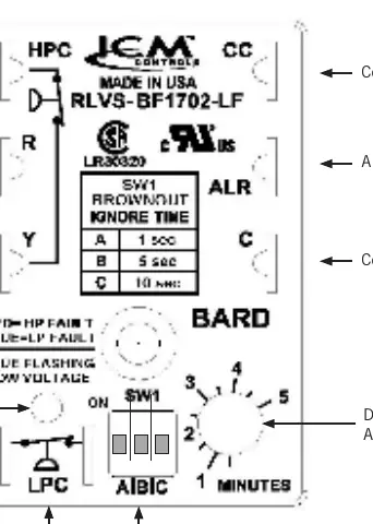
Brownout condition detected
The troubleshooting light will flash blue. This indicates a brownout occurred; check utility or generator power stability.
Before use
- Verify wall structure can support unit weight.
- Ensure 1/4 inch clearance to combustible materials for supply duct.
- Confirm proper phasing for 3-phase models.
- Check refrigerant charge (R-454B).
- Ensure all service panels are accessible.
- Verify all ductwork is insulated.
Specs in practice
- Balanced Climate
- Reduces indoor airflow to increase humidity removal during cooling.
Images and diagrams
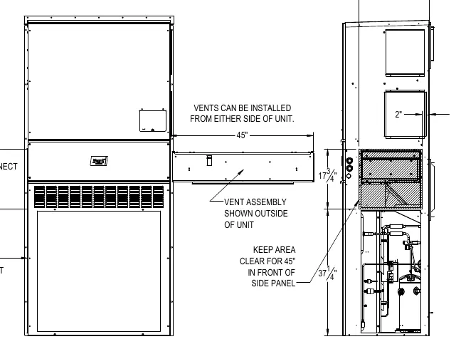
- Figure 12: Vent installation/removal clearance requirements.
- Figure 14: Wall mounting instructions and hole locations.
- Figure 23: Compressor Control Module (CCM) layout.
- Figure 26: Refrigerant Leak Detection System (RDS) components.
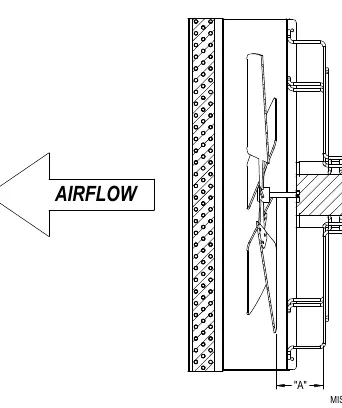
- Figure 30: Fan blade setting dimensions.
Model compatibility
- Requires R-454B refrigerant.
- Requires 2-stage cooling thermostat for Balanced Climate mode.
- Not for use with high-resistance ground (HRG) without consultation.

Manual page author
Michael Turner
Technical manual editor
Reviews PDF manuals for structure, safety notes, and practical product details so readers can find the right information quickly.