HVAC / Air Conditioners
User Manual for Bard Thermostat 1120-445A
Comprehensive user guide for the Bard 1120-445A thermostat. Learn how to adjust temperature, set schedules, manage hold modes, configure installer settings, and understand wiring connections.
Table of contents
Manual images
Click an image to enlargeQuick Start Guide
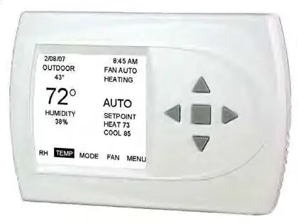
The Bard 1120-445A is a menu-driven thermostat. To adjust the temperature, you must first select a mode (Heating or Cooling). Use the arrow keys to navigate the menu and the center button to confirm selections. The main screen displays the current room temperature, humidity, setpoints, and system status.
Controller Operation
To adjust the temperature, ensure a mode is selected. If not, use the arrow keys to scroll to MODE, press the center button, select the desired mode, and confirm. Once in a mode, use the up and down arrow buttons to change the setpoint, then press the center button to apply the new setting.
To set the date and time, navigate to the MENU from the main screen, select SET DATE AND TIME, and follow the on-screen prompts to adjust the month, day, year, hour, and minute.
Hold Settings
The thermostat supports two types of hold modes for programmable operation:
- Vacation Hold: Allows you to hold a specific temperature for a set period. Access via MENU, select HOLD, then VACATION.
- Permanent Hold: Maintains a temperature indefinitely until manually canceled. Access via MENU, select HOLD, then PERMANENT.
To cancel any hold, navigate to the main menu and select CANCEL HOLD.
Programming
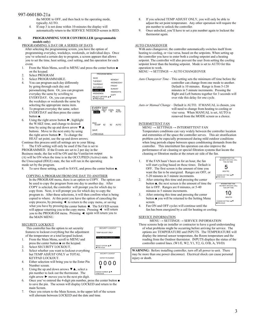
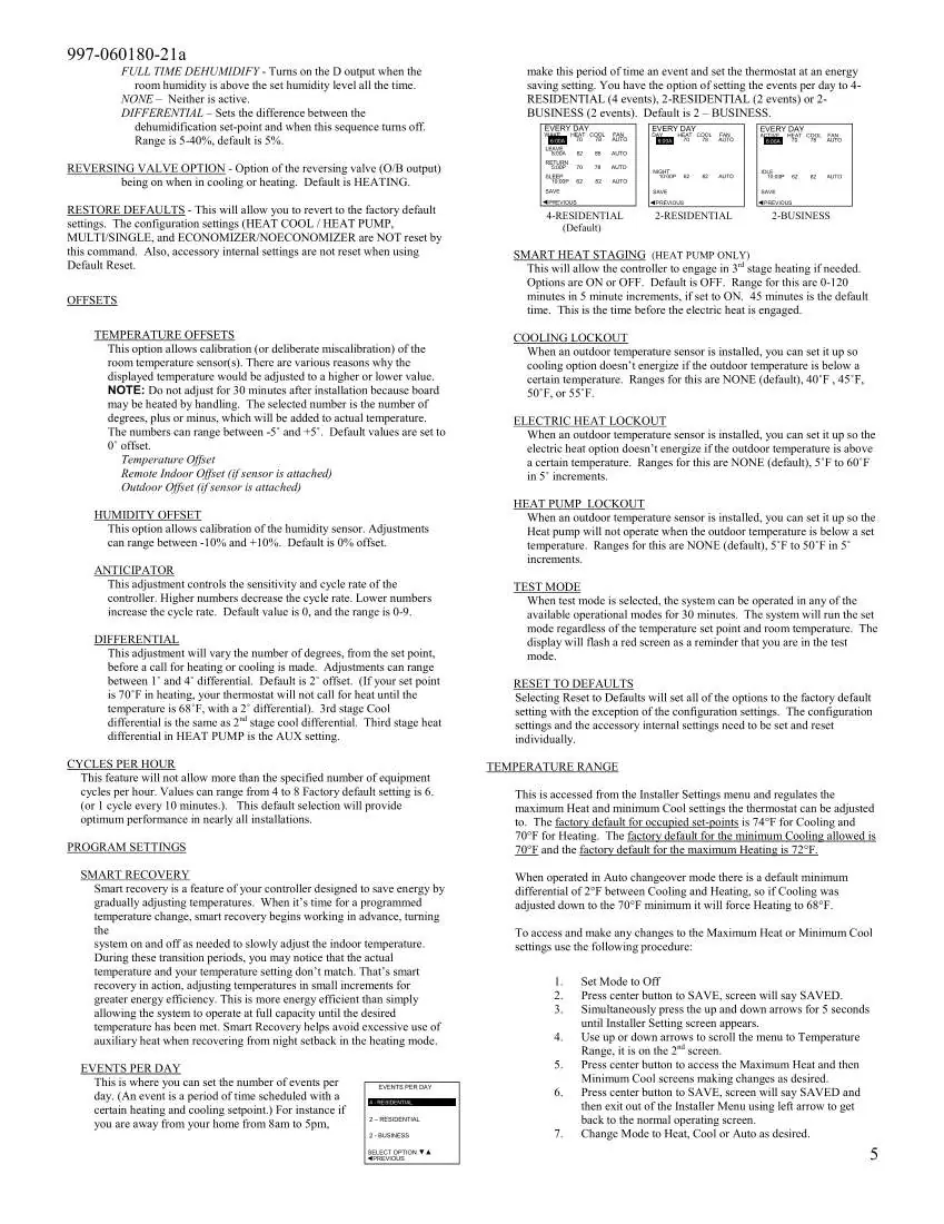
You can program the thermostat for everyday, weekdays, weekends, or individual days. Navigate to MENU, select PROGRAM, and follow the prompts to set the schedule. You can copy programs from one day to another to save time. The system also features Smart Recovery, which gradually adjusts temperatures to reach the desired setpoint by the scheduled time.
Installer Settings
These settings are intended for professional configuration. To access the installer menu, the thermostat must be in the OFF mode. Press and hold both the up and down arrow keys simultaneously for at least 5 seconds. Available configurations include:
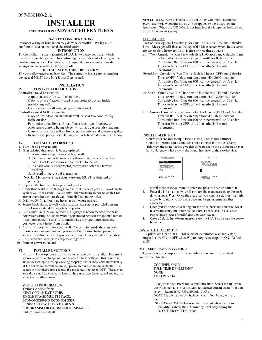
- Model Configuration: Heat/Cool, Heat Pump, Single/Multi-stage, and Economizer settings.
- Temperature Offsets: Calibrate room temperature, remote indoor, or outdoor sensor readings.
- Lockouts: Configure cooling, electric heat, or heat pump lockouts based on outdoor temperature.
- Reset to Defaults: Reverts settings to factory defaults.
Wiring and Installation
The thermostat is a 24V low-voltage controller. It should be mounted approximately 5 feet from the floor on an interior wall, away from direct sunlight, heat sources, or drafts. Ensure both R and C wires are connected. The terminal connections include:
- C: 24V Common
- R: 24V Supply
- W1/E: First Stage Heat
- W2: Second Stage Heat
- Y1: First Stage Compressor
- Y2: Second Stage Compressor
- O/B: Reversing Valve
- A: Ventilation
- G: Fan
- L: Input for CS2000A or compressor fault
- OD: Outdoor Temperature Sensor
- ID: Indoor Temperature Sensor
Practical help
Common problems
Outdoor temperature is not displayed
The outdoor temperature is only displayed if an optional outdoor sensor is installed.
Cannot adjust temperature
Ensure a mode (Heating or Cooling) is selected first. If the thermostat is locked, you must enter the PIN.
Service messages appear on screen
These indicate maintenance intervals (e.g., air filter, humidifier) set by the installer. Clear them by highlighting CANCEL ALARM and pressing the center button.
Before use
- Ensure the thermostat is mounted approximately 5 ft. from the floor.
- Verify that both R and C wires are connected.
- Ensure the thermostat is not mounted near windows, doors, or heat sources.
- Check that the system is powered on.
- If using an outdoor sensor, ensure it is properly wired to the OD and GND terminals.
Specs in practice
- Auto Changeover
- Automatically switches between heating and cooling based on setpoints.
- Smart Recovery
- Gradually adjusts temperatures to reach the setpoint by the scheduled time for energy efficiency.
Images and diagrams
- The main screen shows the current time, outdoor temperature (if installed), humidity, fan status, and current setpoints.
- The keypad uses four arrow buttons for navigation and a center button for confirming selections.
Model compatibility
- Requires 24V AC low-voltage power.
- Compatible with optional outdoor and remote indoor sensors.
- Supports heat pump systems.
- Not a power-stealing device; requires both R and C wires.

Manual page author
Emily Carter
User documentation editor
Prepares concise manual descriptions and highlights the most useful setup, operation, and maintenance information for readers.