HVAC / Ventilation Systems
User Manual for Blauberg Reneo-Fit D 100-E S14 Air Handling Unit
Quick guide for the Blauberg Reneo-Fit D 100-E S14 air handling unit. Includes installation, maintenance, wiring, and troubleshooting instructions.
Table of contents
Manual images
Click an image to enlargeQuick Guide
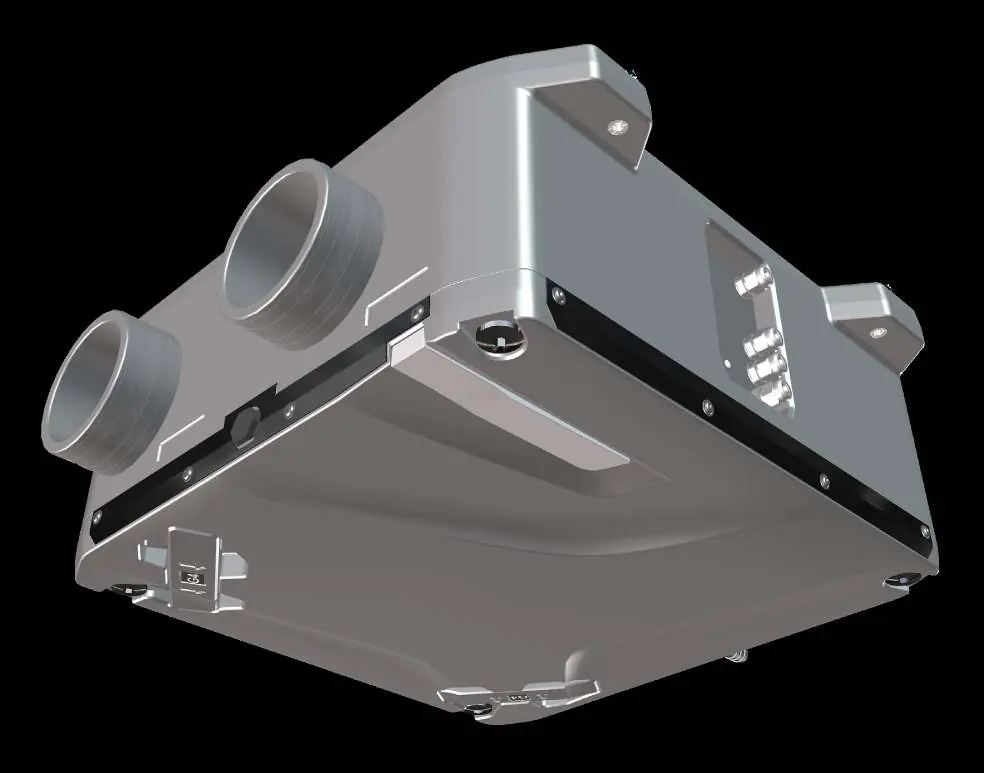
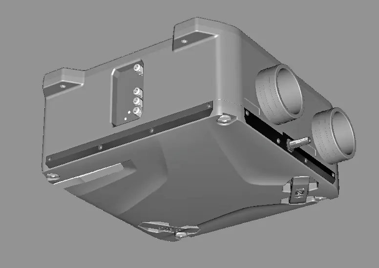
The Blauberg Reneo-Fit D 100-E S14 is a suspended heat recovery air handling unit designed for continuous mechanical air exchange in houses, offices, and public spaces. It is intended for indoor use only and is not suitable for environments with high humidity, such as saunas or swimming pools. The unit features automatic defrosting and heat recovery to improve energy efficiency.
Technical Data
The unit is a Class I electrical appliance with IP22 protection (when connected to ducts) and IP44 for motors. Key specifications include:
- Power Supply: 1 ~ 230 V, 50/60 Hz
- Max Power: 38.07 W
- Max Air Flow: 130 m³/h
- Sound Pressure Level: 32 dBA (at 3 m)
- Weight: 8 kg
- Filtration: G4 / Coarse >60% (Supply filter option F7 / ePM1 60%)
- Operating Temperature: -23 to +40 °C
Installation and Mounting
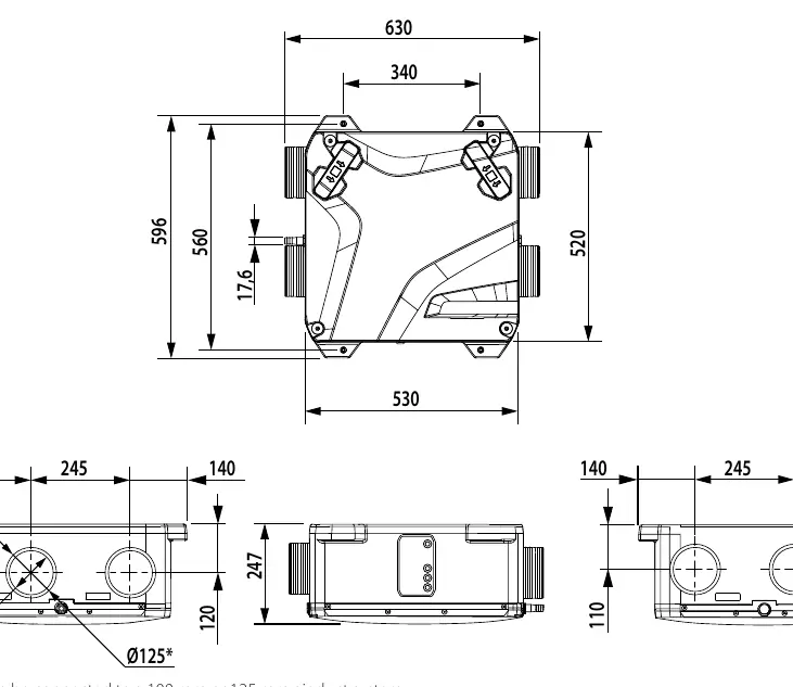
The unit is designed for ceiling mounting only. Ensure there is sufficient space for cover removal and maintenance access.
- Duct Connection: The unit connects to 100 mm or 125 mm air ducts. 100 mm ducts are inserted into the pipes, while 125 mm ducts are placed over them.
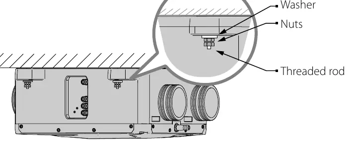
- Mounting: Use anchor threaded rods with nuts at 4 points. Ensure the mounting surface can support the unit weight.
- Condensate Drainage: A U-trap must be connected to the drain pipe and filled with water before operation to ensure proper drainage.
Electrical Connection
All electrical work must be performed by a qualified electrician. The unit must be connected to the mains through a disconnecting device integrated into the fixed wiring system, providing full disconnection under overvoltage category III conditions.
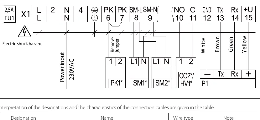
- Route power and control cables through the cable glands in the control box.
- Ensure the external circuit breaker is sized according to the unit's maximum current consumption.
- Refer to the wiring diagram for specific connections of the control panel, sensors, and damper drives.
Maintenance
Regular maintenance is required 3-4 times per year to ensure efficient operation.
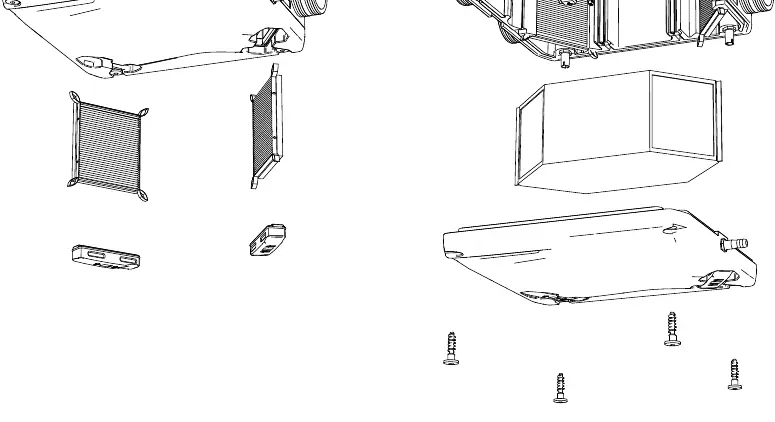
- Filter Maintenance: Clean filters 3-4 times per year using a vacuum cleaner. Replace after two cleanings.
- Heat Exchanger: Clean once per year with compressed air or a vacuum cleaner.
- Fan Maintenance: Clean once per year with a soft cloth or brush. Do not use water or aggressive solvents.
- Air Intake Devices: Check and clean supply grilles twice per year.
- Ductwork: Clean or replace duct components once every 5 years.
Troubleshooting
If the unit fails to operate, check the following:
- Unit does not start: Verify power supply connection, check for a jammed motor, or check if the fan has overheated.
- Circuit breaker trips: Check for a short circuit in the electric circuit.
- Noise/Vibration/Reduced Flow: Clean the fan impellers, tighten screw connections, or clean/replace clogged ventilation components.
Manufacturer information
Blauberg Ventilatoren
Practical help
Common problems
Unit does not start
Ensure power supply is connected correctly. Check for a jammed motor or fan overheating; disconnect power, resolve the issue, and restart.
Automatic circuit breaker trips
Switch off the unit and check for a short circuit in the electrical wiring.
Noise, vibration, or reduced air flow
Clean the fan impellers, tighten loose screw connections, or clean/replace clogged air ducts, diffusers, and grilles.
Before use
- Ensure installation is performed by qualified personnel.
- Verify the power supply voltage matches the unit specifications.
- Check the impeller, casing, and grille for visible damage.
- Ensure the U-trap is installed and filled with water.
- Verify that the unit is mounted securely to the ceiling.
- Ensure the casing is free of foreign objects.
Specs in practice
- Max. air flow
- 130 m³/h; maximum ventilation capacity.
- Sound pressure level
- 32 dBA at 3 m; noise level during operation.
- Filtration class
- G4 / Coarse >60%; standard filtration level for intake and exhaust air.
Images and diagrams
- The wiring diagram illustrates connections for the external control panel, CO2/humidity sensors, fire alarm contact, and damper drives.
- The condensate drainage diagram shows the required U-trap installation to prevent air leakage and ensure proper water drainage.
Model compatibility
- Compatible with 100 mm or 125 mm air duct systems.
- Not suitable for high-humidity environments like saunas, swimming pools, or greenhouses.
- Requires qualified personnel for installation and electrical connection.

Manual page author
Emily Carter
User documentation editor
Prepares concise manual descriptions and highlights the most useful setup, operation, and maintenance information for readers.