Power / Batteries & Chargers
User Manual for Utilitech 7131-04 Ventilation Fan with Humidity Sensor
Quick guide for the Utilitech 7131-04 ventilation fan. Includes installation steps for new and existing construction, operating instructions for humidity sensing and full-speed modes, maintenance tips, and troubleshooting.
Table of contents
Manual images
Click an image to enlargeImportant Information
The Utilitech 7131-04 is a ventilation fan designed for bathroom use, featuring an integrated humidity sensor. Key specifications include an airflow of 100 CFM, a sound output of 1.5 sones, and a power consumption of 17W. It operates on a 120V, 60Hz power supply. This unit is not intended for use in kitchens or with solid-state control devices like dimmers or remote controls.
Safety Information
- Always disconnect the power supply at the circuit breaker before servicing or cleaning.
- Installation must be performed by a qualified person in accordance with local building and electrical codes.
- Do not install in ceilings with insulation greater than R40.
- Ensure the fan is vented to the outdoors; do not vent into attics, crawl spaces, or garages.
- If installing over a tub or shower, the unit must be connected to a GFCI-protected branch circuit and installed at least 3 ft. 3-1/4 in. (1 m) from the showerhead.
New Construction Installation
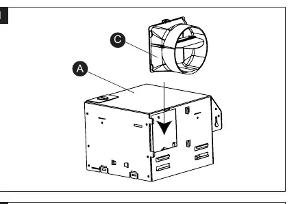
- Attach the duct connector (C) to the fan housing (A).
- Remove the wiring box cover and the wiring knockout.
- Position the fan housing (A) next to a ceiling joist or wall stud. Ensure it is level and the bottom edge is flush with the ceiling or wall board.
- Secure the housing to the joist using wood screws through the metal tabs.
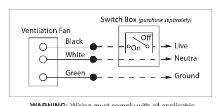
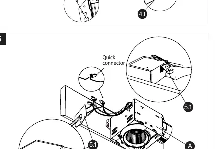
- Connect house wiring to the fan using the provided quick connectors. Ensure proper wire connections (refer to the wiring diagram).
- Connect a 4-inch circular duct to the duct connector and secure with duct tape or a clamp.
- Attach the grille (B) by pinching the mounting springs and inserting them into the slots on the housing.
Existing Construction Installation
- Remove the existing fan and measure the opening to ensure it accommodates the 7-1/2 in. x 7-1/4 in. housing dimensions.
- If necessary, cut an opening of 7-3/4 in. x 7-1/2 in.
- Attach the duct connector (C) to the fan housing (A).
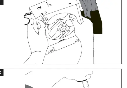
- Remove the fan motor assembly from the housing to facilitate installation.
- Remove the wiring box cover and knockout.
- Pull house wires through the wiring box and connect using quick connectors.
- Connect the 4-inch duct to the connector.
- Insert the housing into the ceiling/wall opening and secure it to the joist or stud with wood screws.
- Reinstall the fan motor assembly and plug it back into the housing.
- Attach the grille (B) using the mounting springs.
Operating Instructions
The fan features two modes controlled by the wall switch:
- Humidity Sensing Mode: Flip the wall switch to the ON position. The LED indicator in the grille will be BLUE. The fan will automatically turn on when humidity exceeds the user-adjustable set-point and turn off when it drops below that level.
- Full Speed Mode: Toggle the wall switch on and off. The LED indicator in the grille will be AMBER.
- Off: Flip the wall switch to the OFF position.
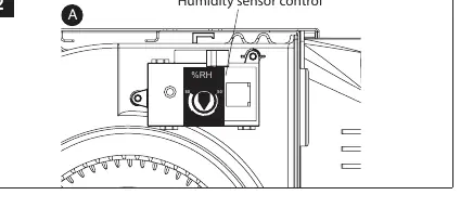
To adjust the humidity sensitivity, use the selector dial located on the humidity sensor control inside the fan housing.
Care and Cleaning
Routine maintenance should be performed at least once a year:
- Disconnect power before cleaning.
- Remove the grille (B) by squeezing the mounting springs and pulling it down. Wipe with a damp cloth.
- Use a vacuum cleaner to remove dust and dirt from the fan housing (A). Carefully clean around the humidity sensor control to maintain accuracy.
- Wipe the housing with a damp cloth and dry thoroughly.
- Do not use solvents or harsh chemicals. Do not allow water to enter the motor.
Troubleshooting
If you encounter issues, check the following:
- Fan is louder than expected: Ensure the CFM rating matches the room size, check for sharp bends in the duct within 18 inches of the discharge, or ensure the fan is securely attached.
- Abnormal sound/vibration: Ensure the housing and grille are securely attached.
- Not clearing humidity: Ensure there is sufficient airflow intake (e.g., slightly open door/window) and that the humidity sensing mode is selected.
Manufacturer information
Utilitech
Practical help
Common problems
Fan seems louder than it should be
Check that the CFM rating matches the room size, ensure there are no sharp bends in the duct within 18 inches of the fan discharge, and verify the fan body is securely attached to the joists.
Abnormal sound or vibration
Ensure the fan housing is securely attached to the ceiling joists or wall studs and that the grille is pushed upward until firmly attached.
Fan is not clearing humidity
Ensure there is sufficient airflow intake in the room (e.g., leave a door or window slightly ajar) and verify that the humidity sensing mode is selected (LED indicator should be blue).
Before use
- Ensure power is turned off at the circuit breaker.
- Verify all parts are present (Fan housing, Grille, Duct connector).
- Check that the ceiling/wall opening is the correct size (7-3/4 in. x 7-1/2 in. for new construction).
- Ensure 4-inch ducting is available.
- Confirm wiring matches local codes (14 AWG minimum).
Specs in practice
- Sound output
- 1.5 sones - a measure of the noise level; lower is quieter.
- Power consumption
- 17W (0.3A) - the electrical power required to operate the fan.
- Humidity sensor tolerance
- +/- 10% - the margin of error for the humidity sensing feature.
Images and diagrams
- Wiring diagram shows the connection of house wires to product wires using quick connectors.
- Installation steps illustrate how to secure the housing to joists using wood screws.
- Humidity sensor control dial is located on the fan housing for manual adjustment.
Model compatibility
- Not for use in kitchens.
- Do not use with solid-state control devices (e.g., dimmers, remote controls).
- Requires 120V, 60Hz power supply.
- Do not install in ceilings with insulation greater than R40.

Manual page author
David Miller
Documentation analyst
Organizes user manual content into clear summaries, with attention to model details, product context, and everyday usability.